
If you need a linear motion system that can travel at high speed over long lengths, what solutions come to mind first? Belt drives? Rack and pinion systems? Linear motors?
If the application requires high thrust force, belt drives won’t suffice, and if high positioning accuracy is important, rack and pinion systems are out. Linear motors can produce high forces and have excellent positioning accuracy, but are susceptible to contamination.
Chances are, ball screw drives didn’t come to mind because of their speed and length limitations. But in some applications, the requirements for thrust force, positioning accuracy, or protection from contamination make a ball screw drive the best choice. But how can the length vs speed dilemma be resolved?
Length and Critical Speed: An Inverse Relationship
As discussed in a previous post, critical speed is often the limiting factor in selecting a ball screw for a given application. Like any long, cylindrical object, a ball screw will naturally sag in the middle due to its own weight. When the screw turns, it begins to whip, or bend, like a jump rope. The speed at which the screw starts to encounter bending vibrations is known as its critical speed.
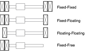
The calculation for critical speed takes into account the screw’s diameter and length, as well as the type of end bearings supporting the screw.
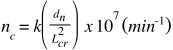
nc = critical speed
k = factor based on end support bearings
dn = root diameter of ball screw
Lcr = unsupported length of ball screw
In this calculation, length is defined as the screw’s unsupported length. If the ball nut is not preloaded, the unsupported length is the distance between end bearings. If the ball nut is preloaded, the unsupported length is the distance between the ball nut and the least rigid bearing support.
From the equation, you can see that the critical speed and unsupported length have an inverse square relationship. Put simply, by halving the unsupported length, the critical speed increases by a factor of four. Therefore, the most effective method to increase the critical speed is to reduce the unsupported length. But how can you reduce the unsupported length of the ball screw without sacrificing the travel length?
Long Travel vs. High Speed: You Can Have Both
Ball screw supports can solve this length-speed dilemma. These floating supports (typically used in sets of 2, 4, or 6) are located on each side of the ball nut, and are connected in a way that allows them to extend to an equal spacing on one side of the ball nut, as the nut travels in the opposite direction, reducing the unsupported length proportionally. In the direction that the ball nut is traveling, the supports stack up at the end of the screw to provide the least interference with the stroke.
Based on the critical speed equation, adding just one set of ball screw supports (one support on each side of the ball nut) will quadruple the screw’s critical speed! Cutting, routing, and other operations in metal manufacturing and woodworking are the most common applications for ball screw supports, due to their need for high thrust forces and good positioning accuracy while moving long distances at fast speeds.
It’s important to remember that ball screw supports require additional space, and to calculate the length of the screw accordingly so the desired travel length can be achieved. Each ball screw support typically adds three to five inches of “unusable” length, so one set of supports increases the screw length by six to ten inches. This also negates a small amount of the reduction in unsupported length, but the addition of screw supports will rarely have an adverse affect on the final ball screw selection. In some cases, the use of ball screw supports will allow you to select a smaller diameter ball screw and reduce the requirements on other parts of the system, such as couplings, bearings, or motor-drive components.
When your application requires high thrust forces, high positioning accuracy, or contamination protection, but the limitations of length and speed seem to exclude ball screws as a suitable solution, talk to your screw manufacturer or machine builder about adding ball screw supports to the assembly. They could help you avoid the length-speed compromise.

Another way to solve this problem is to make the ball screw stationary and rotate the ball nut. We have done this on several projects successfully. It is a good idea to tension the ball screw to prevent excessive sag.
Randall, that is a great idea, and it would provide the benefits that you describe. But I can see that the implementation could be a challenge in some instances.
Hello Randall, and thanks for reading and commenting! You’re correct, rotating the ball nut is another way to overcome the length/speed limitations of ball screws. This topic might make a good follow-up post. Stay tuned…
I have never seen such a product.
Can you provide a link or a part number so i can find an example to look at?
Sounds super useful.
Hi,
What is a floating ball screw support?
The conditions are defined well but the actual design is not discussed.
I find nothing on the internet when searching ball screw support…….
Just trying to understand the logic here.
-B
Hi,
What is a floating ball screw support?
The conditions are defined well but the actual design is not discussed.
I find nothing on the internet when searching ball screw support…….
Just trying to understand the logic here.
-B
Mr Collins, I am hobbyist and want to build a 3000mm c 1300mm x 300mm CNC router.
I am here because I am more interested in accuracy, zero backlash and repeatability instead of speed.. That being said, I would like to drive the 3000mm axis with a precision 25mm x 20mm x 3000mm ball screw but also concerned about whip.
Prior to reading this article I was also thinking about somehow supporting the ball screw on a sliding bearing that would be pulled out at either end and move with the ball screw at to set distance.. I figured I could mount the bearing supports on a rail.
I’m still contemplating what I would use to pull the bearings from either end toward the middle of the ball screw. Perhaps I could use a steel cable?
Where do I get a 25mm ball screw support?
I was just think too that if I support the ball screw I might be able to get away with a much thinner ball screw? Maybe a 15mm x 20mm?
What are your thoughts on all this?
Thanks and kind regards,
Tom Frazier
Hi Tom,
Your idea is right on track. I’m familiar with one linear actuator manufacturer, Bosch Rexroth, who offers screw supports in a design very similar to what you’re describing on their “MKK” series ball screw actuators. (There may be other manufacturers who offer similar designs as well, such as Parker Hannifin.) A steel cable would probably do the trick for moving the supports back-and-forth as the nut travels. You just want something that will not flex at the lengths you require. And I would say that for the screw supports, since they’re not contributing to the load-carrying capacity or positioning of the nut, they don’t need to be a specific material or size – just large enough on the i.d. not to interfere with the screw shaft and suitable for mounting to the bearings on the rail.
Good luck in your design!
-Danielle