
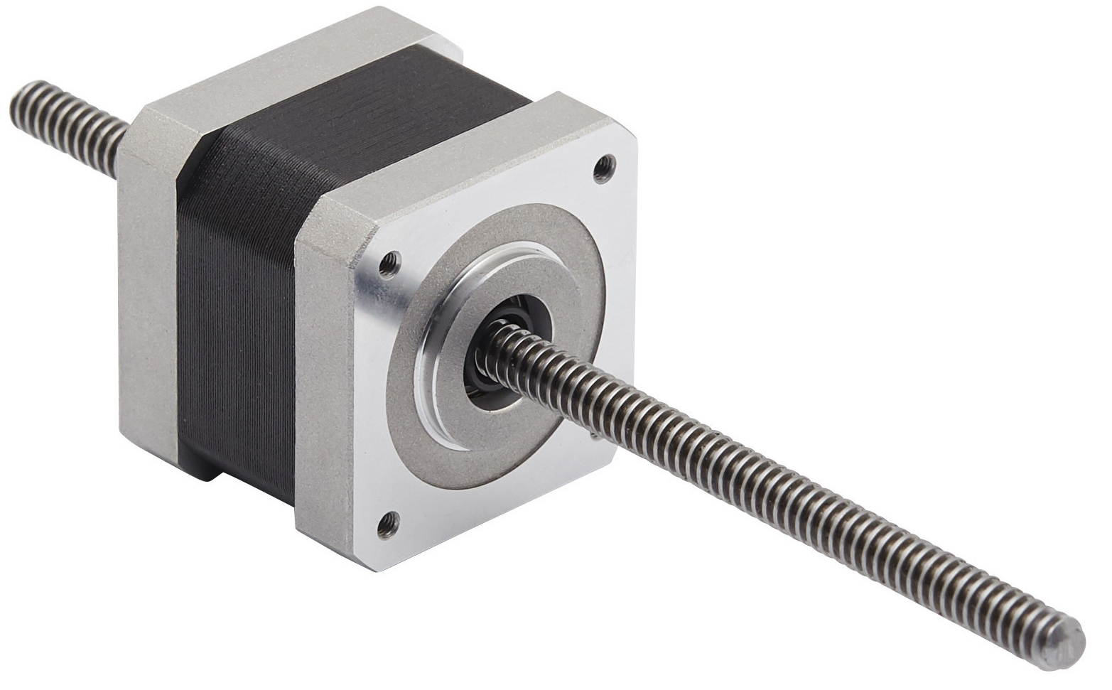
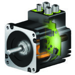
Image credit: ElectroCraft
When it comes to electromechanical linear actuators, integrated designs offer space savings, reduced complexity, and lower total cost of ownership with fewer parts required for repair or replacement. One such design that’s found multiple uses in medical, 3D printing, and assembly applications is the hybrid stepper motor linear actuator, which combines a ball or lead screw with a hybrid stepper motor.
Don’t confuse hybrid stepper motor linear actuators with can stack stepper motor linear actuators. The force vs. speed characteristics, efficiencies, and cost differences between actuators that incorporate hybrid stepper motors and those that use can stack stepper motors can be substantial, although each technology has unique strengths and best-fit applications.
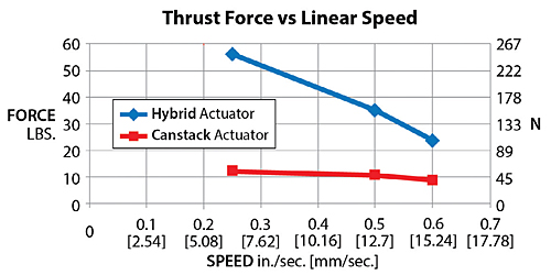
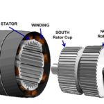
Image credit: Haydon Kerk
Hybrid stepper motor linear actuators — also referred to as linear hybrid stepper actuators and stepper linear actuators — offer a wide variety of options, not only in features such as custom machining and materials, but also in their basic design and operation. Case in point: There are three main types, of hybrid stepper actuators — captive, non-captive, and external (also referred to as a motorized lead screw) — with some manufacturers offering additional variations for more specific uses. Below is a quick summary of each type, and for a more in-depth explanation, check out this article, which details the construction and operation of various integrated motor-screw designs.
- Captive: In this design, the lead screw nut is integrated directly into the motor. The screw is connected to a spline shaft, so when the motor turns, the screw is prevented from rotating, and linear motion is produced, allowing the screw to extend and retract from one end of the assembly.

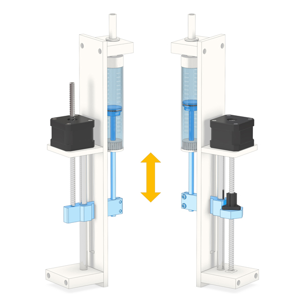
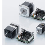
Image credit: Nanotec - Non-captive: In this type type of actuator, the ball or lead screw nut is integrated into the motor (or mounted to the face of the motor) and doesn’t travel along the screw. Instead, the screw must be prevented from rotating (typically by the attached load), and when the motor and nut turn, the screw travels linearly, back-and-forth “through” the motor-nut combination. Alternatively, if the screw is fixed so that it doesn’t travel, the assembly essentially becomes a driven nut design, where the motor’s rotation causes the motor-nut assembly to travel back-and-forth along the stationary screw.
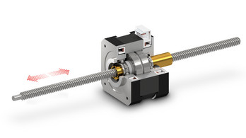
Image credit: Nanotec - External: These actuators use a motor with a hollow shaft and integrate one end of the screw directly into the motor, so the nut remains external to the motor. Like a traditional screw-motor setup, the motor’s rotation causes the screw to turn, which advances the nut (and the load) along the length of the screw shaft. In this design, the opposite end of the screw (not attached to the motor) is unsupported, which is acceptable for light loads and short stroke lengths. However, many applications will require support for the free end of the screw, along with a linear guide to support any radial loads.
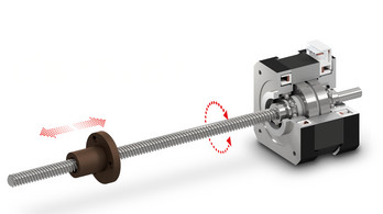
Image credit: Nanotec
Like the stepper motors on which they’re based, hybrid stepper linear actuators are sized according to the NEMA ICS 16-2001 standard, which specifies the motor mounting dimensions, such as flange size and bolt circle diameter. The most common sizes for hybrid stepper actuators in general motion applications are NEMA 17 and 23, although some manufacturers offer sizes ranging from NEMA 8 up to NEMA 34.
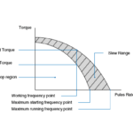
Because the NEMA standard doesn’t address the length of the motor, manufacturers can offer several torque ranges for the same NEMA frame size by increasing the stack length of the motor — in other words, multiple rotors and stators can be “stacked” in the same motor housing. The result is a motor with the same frame dimensions (albeit slightly longer) that has higher torque and force capability. However, it’s important to note that in multiple-stack stepper motors, torque production falls off more quickly as motor speed increases than in single-stack designs.
For applications that can benefit from even further integration, with reduced complexity, assembly time, and cost, some manufacturers offer hybrid stepper linear actuators with drive electronics and controller functions integrated into the motor. And recall that hybrid stepper motors can operate with microstepping control for even higher resolution and in closed-loop mode when position feedback is required.
With their wide range of designs and options, it’s not surprising that hybrid stepper motor linear actuators are used in all types of industries and applications. Here are a few examples of applications where these actuators excel, thanks to their compact size, precise positioning, and good speed-force characteristics.
Precision metering and dosing pumps
Whether for the medical, semiconductor, or assembly industries, hybrid stepper actuators are an ideal solution for driving small, precise pumps, thanks to their extremely compact footprint and ability to move at high speeds with high precision.
XY tables
One of the key design principles for an XY table is to keep the footprint as compact as possible, and hybrid stepper linear actuators contribute to this goal by keeping the drive system small while providing high thrust forces and positioning accuracy.

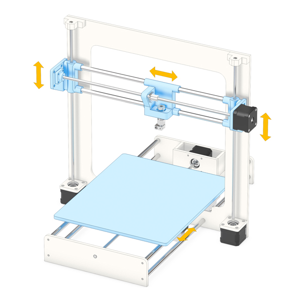
CNC machines and 3D printers
Although one takes material off (CNC machines) and the other adds material (3D printers), both applications require very high positioning accuracy and reliability — two performance areas where hybrid stepper motor actuators excel, especially when used with microstepping control in a closed-loop system.
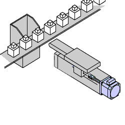
Diverting and Sorting
In conveyor applications, there are often stations that require diverting or sorting products for quality issues or manufacturing flow. In these applications, hybrid stepper linear actuators provide fast extension and retraction with good thrust force and simple controls.

Leave a Reply
You must be logged in to post a comment.