
Travis Schneider, Product Manager, Automation Group, Parker Hannifin
Understanding the pros and cons of different linear screw drive actuators helps you make the best choice for your application.
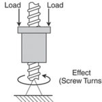
Screw drivetrains are among the most common types of electric linear actuation used in industry today. However, given the range of options available, finding the best solution for a specific application can be complicated. The first step in simplifying the selection process is to understand the various technologies available. Each of the three major screw drivetrains have their own advantages and disadvantages. Each screw acts as a linear force generation device, taking rotary torque input from a motor and converting it to linear thrust.
Ballscrews
Many linear motion applications use ballscrews to convert motor torque into linear thrust; this is primarily due to their commercial availability, ease of manufacture, high efficiency and load-life characteristics. Mechanically, the ballscrew is composed of a metal screw and nut, which uses metal ball bearings as the mating interface between threads. Several manufacturing techniques are used to manufacture a ballscrew; the most common ones are rolling, grinding and whirling. If properly designed, ballscrews are ideal for industrial applications with high duty cycles that also require high thrust—much like applications for which one would typically use an air cylinder or even a hydraulic cylinder.
Leadscrews
Lead screws are often the mechanical drivetrain of choice for applications that require relatively low precision and a low-duty cycle for a low cost. Leadscrews are composed of a metal screw that interfaces with a softer nut (often plastic or bronze). Primary manufacturing techniques are either rolling or grinding. Given their wear characteristics, leadscrews are not always ideal for industrial applications, but they are well suited for applications that require low duty cycle adjustments to positions or a self-locking drivetrain.
Rollerscrews
A rollerscrew is composed of a screw and an interfacing nut, just like in a ballscrew; however, instead of using ball bearings as the interface between nut and screw, small rollers rotate to provide contact between them. This nut technology allows for line contact between rollers, nut, and screw, which makes this technology superior to ballscrews in terms of shock load and overall stiffness. The tight machining tolerances and limited number of manufacturing techniques involved in producing rollerscrews makes manufacturing them quite costly; as a result, manufacturing lead times are much longer than those for ball- or leadscrews. Rollerscrews are often reserved for applications that demand the ability to handle high loads and require extremely long life.
Most design engineers can determine whether or not leadscrews are appropriate for a specific application quickly and easily. So the focus here will be on the differences between ballscrews and rollerscrews. However, in application, there’s more to take into account than just the type of screw used in the actuator.
Typical application example
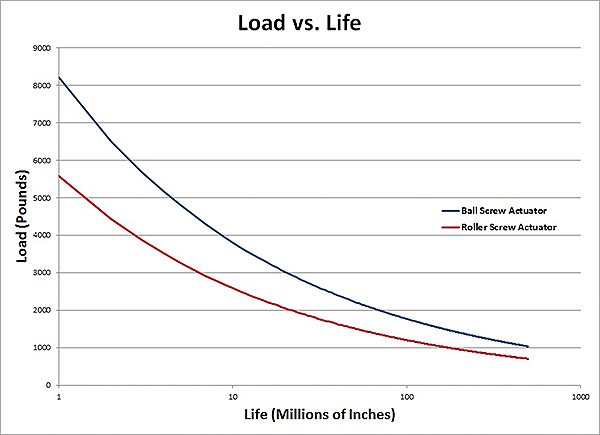
To illustrate the actuator selection process, let’s consider an application that requires 1,000 lbƒ of continuous thrust over a 10-in. stroke, moving at 12 in./sec at 100% duty cycle. In this application, the objective is to maximize the life of a particular actuator. Given this application’s high duty cycle, this analysis will focus on ballscrew and rollerscrew options with similar pitches and packaging. Figure 1 compares results from two different actuator solutions:
• ballscrew with a 95-mm square frame
• rollerscrew with a 102-mm square frame
The load versus life comparison in Figure 1 demonstrates that the ballscrew, though slightly smaller in frame, actually has a longer expected life than a similar rollerscrew actuator. This is largely due to the optimized packaging of the ballscrew within the actuator body. The ballscrew design’s advantages are even more pronounced when cost is factored in.

An engineering approach
The results shown in Figure 1 make choosing between a ballscrew and a rollerscrew solution fairly straightforward. Relevant performance metrics can also help in the selection process, a decision that is too often made based on product labeling and initial perception of screw technology. In actual application, it’s essential to take into account what is most important to achieving the desired motion, life, delivery or price point.
As an example, here is a straightforward three-step process that compares a ballscrew with a rollerscrew actuator.
Step 1: Identify relevant performance metrics
Performance metrics are quantifiable outputs that measure the appropriateness of one technology (or in this case, actuator) over another for an intended application. Metrics that benefit the application, such as actuator life, should be maximized; metrics that hinder the application, such as cost, should be minimized.
In our typical application example, we examined three metrics: actuator life, actuator frame size and cost. Table 2 lists the relative performance of two electric cylinders to be evaluated.

Step 2: Apply the actuator performance equation for each solution
The relatively simple performance calculation can be used to quantify the relative performance of each actuator solution. Using the calculation form shown in Step 3, characteristics that are ideally maximized, such as actuator life, are input in the numerator, with the maximum across all actuator options input as the denominator. In contrast, characteristics that are ideally minimized, such as cost, are input in the denominator, with the minimum across all actuator solutions input as the numerator.
Step 3: Score it
Actuator performance calculation

This calculation takes into account each critical aspect of actuator performance and quantifies it. Weights can be applied to each of the metrics by assigning the coefficients (A, B, C and D) a relative value. If using this equation with no weights, the best solution should yield the score closest to 1.
This calculation can also be used to weigh one metric higher than another. Given this model, the higher the performance score is, the more ideal the actuator will be in application. Using this example, as well as the metrics of life, frame width, and cost with even weight, results in the following calculations:

Although these two electric cylinders might initially appear to offer comparable performance, once their relative merits are weighed using the actuator performance calculator, the differences become quite evident.
In addition to performance and cost considerations, it’s important to take into account how easy it is to source a given technology. Ball- and leadscrews are widely available from numerous suppliers around the world. In contrast, few screw manufacturers produce rollerscrews. When designing a motion application in a global market, the availability of a given technology should be a deciding factor.
Parker Hannifin Automation Group
www.parker.com


Leave a Reply
You must be logged in to post a comment.