
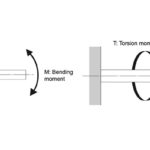
Like other linear motion components where rolling elements ride in raceways, ball splines can be supplied with preload. In the case of a ball spline, the main purpose of preload is to reduce angular backlash — clearance in the rotational direction — when torque is applied.
Without preload, ball splines have a small amount of backlash, or “play,” when they rotate, due to clearance between the balls of the spline nut and the grooves on the spline shaft. So when torque is applied, the component attached to the load (either the spline nut or the spline shaft) will begin to rotate, but the mating component doesn’t immediately follow. Backlash leads to lower stiffness and reduced positioning accuracy in the rotational direction — especially when the direction of rotation changes.
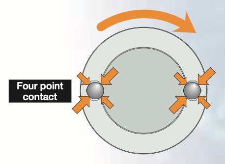
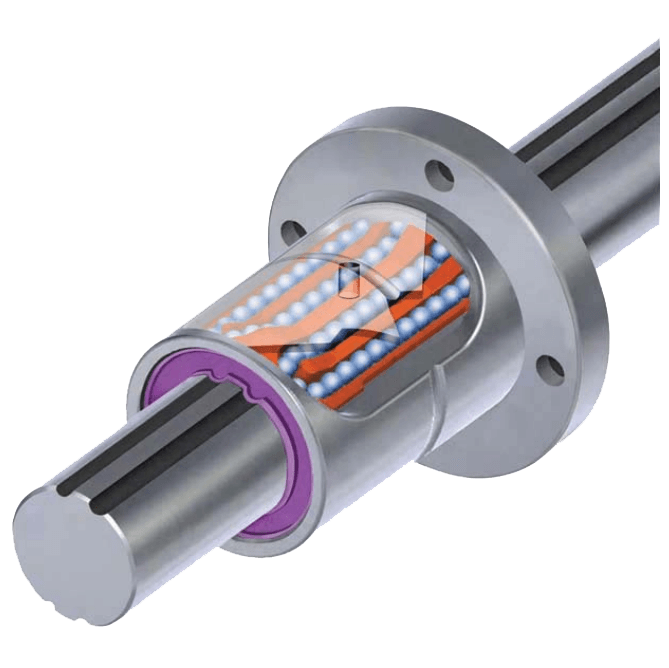
Image credit: IKO
Recall that balls riding in raceways can have either Gothic arch or circular arc contact geometry. While these geometries are often associated with the raceways of profiled rail linear guides, they also apply to the grooves of ball splines.
In general, larger diameter ball splines employ the Gothic arch groove design, which provides four points of contact between the ball and the raceway. This four-point contact eliminates clearance and provides higher load capacities. However, the Gothic arch design can lead to higher differential slip, which increases friction.
Conversely, smaller diameter ball splines typically use circular arc groove geometry — which provides two points of contact between the ball and the raceway — for its lower friction and smoother running characteristics.
Differential slip occurs because the contact area between the ball and the raceway is an ellipse. This elliptical contact area means the diameter along which the ball rolls will vary, and so the rolling speed will vary, depending on which portion of the ellipse is engaged. This causes the ball to slip rather than roll and results in sliding friction — referred to as differential slip.
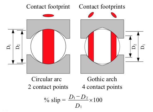
Image credit: Alexander Slocum
The larger the difference between the rolling diameters, the more differential slip the ball experiences. Because the difference between rolling diameters is larger in Gothic arch designs than in circular arc versions, the Gothic arch design experiences higher differential slip and higher friction.
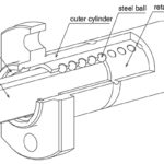
Regardless of which groove geometry is used, preload can be applied to a ball spline to ensure that angular backlash is completely removed and to increase the rigidity of the assembly. Ball spline preload is typically created by varying the diameter of the balls in the spline nut, in a manner similar to that of a ball nut or recirculating ball or roller bearing carriage.
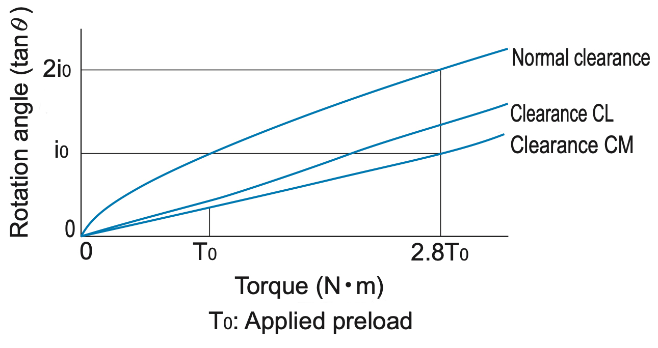
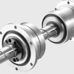
Image credit: THK
Since the primary purpose of preload in a ball spline is to reduce angular backlash, manufacturers typically offer “normal,” “light,” and “medium” preload amounts (or some variation of these classifications). While most manufacturers define preload in terms of microns of angular clearance, the amount of preload force classified as “light preload” is generally around 2 percent of the spline nut’s basic static load rating.
Preload is most often recommended when the spline shaft will experience vibrations or oscillating loads, since these can cause significant, premature wear on the spline shaft grooves and the balls when they have clearance. Light preload increases positioning accuracy in the rotational direction, while medium preload is recommended for more severe vibrations or when high rigidity is needed. It’s important to note that some manufacturers recommend using spline shafts with clearance (no preload) when two shafts are used in parallel.


Leave a Reply
You must be logged in to post a comment.