
When a linear guide, such as a round shaft or profiled rail, deflects or sags, the bearings that travel along the guide experience edge loading (a higher load concentrated at the ends of the bearing), which can cause rough, irregular movement, increased wear, and reduced bearing life. And when a linear guide is incorporated into a linear actuator, deflection in the actuator housing or body translates to the guide, causing the same performance issues.
To avoid excessive deflection, linear systems should be mounted according to manufacturer’s specifications, which include tolerances for flatness and straightness. Ideally, this would entail mounting the actuator or guide with continuous support along its entire length. But in cases where full support isn’t feasible — often due to design or space constraints — the following beam deflection equations can provide an estimate of how much deflection will be caused by the application’s mounting and loading conditions.
Beam deflection equations for round shaft guides and gantry systems
One way to prevent deflection in round shaft guides is to use shaft supports. But these add cost and negate one of the benefits of using round shafts: open space under the shaft for other structural or machine components.
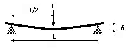
For this reason, round shaft guides are often supported only at the ends, which is referred to as simply supported mounting. But with the full length of the shaft unsupported, the shaft will deflect due to its own weight. And when an external load is added, the load will cause additional deflection as it travels along the shaft, with maximum deflection occurring when the load is located at the center of the shaft’s length.
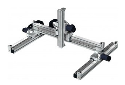
Simply supported mounting also occurs in gantry systems, which are made up of two X (base) axes, with a Y (cross) axis mounted between them. The Y axis is mounted only at its ends, in a simply supported arrangement. Like the simply supported shaft, the cross axis of a gantry system deflects due to both its own weight and the applied load, with maximum deflection occurring when the load is located at the middle of the axis (typically one-half of the stroke length).
For a simply supported beam (round shaft guide or a gantry cross axis), the maximum deflection is the sum of deflection due to the beam’s own weight, plus deflection due to the load:
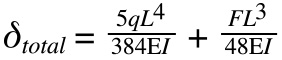
E is the modulus of elasticity of the material, also referred to as Young’s modulus. Its units are N/m2 or lbf/in2. Modulus of elasticity is often provided by the manufacturer.
I is the planar moment of inertia (also referred to as “second moment of area”) of the guide or actuator. Its units are m4 or in4. Planar moment of inertia formulas for common shapes can be found here.
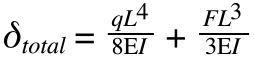
The most basic mounting and loading arrangement is simply supported with a single point load. But linear guides and systems typically use two bearings per guide in order to improve moment loading capability and overall load capacity.
In this arrangement, the load is split between the two bearings, and maximum deflection occurs in two places: at the location of each bearing when the center of the load is located at the middle of the system’s length.
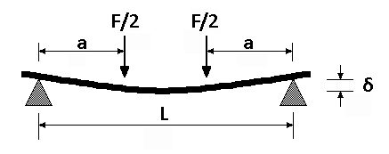 When two bearings are used on a single guide, deflection due to the weight of the beam (guide or axis) plus deflection due to the applied load is calculated as:
Beam deflection equations for Cartesian systems and telescoping guides
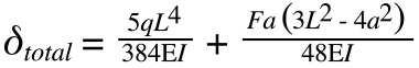
A cantilevered beam is supported only at one end, with maximum deflection occurring when the applied load is located farthest from the supported end. Like simply supported beams, cantilevered beams experience deflection due to both their own weight and the weight of the applied load.
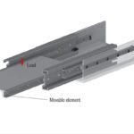
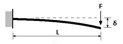 Cantilevered beam scenarios are found less often in linear guide and actuator applications. But two types of linear systems are inherently cantilevered: telescoping guides and Cartesian systems. In a Cartesian system, the base, or X, axis is fully supported, and depending on the Cartesian configuration, either the second (Y) or third (Z) axis will be cantilevered.
For a cantilevered beam, deflection due to the weight of the beam (telescoping guide or Cartesian axis) plus the load is calculated as:
Note that deflection calculations for compound telescoping guides are more complicated than the cantilevered beam deflection equations given here, due to intermediate supports and varying cross-sections along the length of the guide. The equations given here are for simple telescoping applications. For more complex arrangements, manufacturers often provide deflection calculations specific to their telescoping guide designs.


Leave a Reply
You must be logged in to post a comment.