Updated May 2018 || When it comes to linear guide wheels, here’s what you need to know to ensure a smooth design.
Linear guide systems are chosen for an application based not only on their precision and speed characteristics, but also on a host of other operating conditions such as environment, length, speed, duty cycle, and temperature, to name a few. Guide wheel systems should not be overlooked; in many applications and environments they have notable advantages.
Well-known for their ability to outperform recirculating ball technology in harsh environments due to their completely enclosed ball bearings and raceways, guide wheel systems also have lesser known distinct advantages. They routinely operate in environments with low noise level requirements, high (up to 500° F) or low (as low as -94° F) operating temperatures, washdown practices, and straightness tolerances as tight as ±0.001 in. (±0.03 mm). Compared to other linear guide technologies, guide wheels have less friction, are much faster to assemble and are cost efficient.

By matching the component properties of a guide wheel system to a given application, engineers can ensure trouble-free operation over the system’s predicted lifespan, as well as reduced costs, lead time and field failures. The types of wheel and track selected must be matched to all application requirements, including environment, loads, accuracy, lifecycle and cost. The following is an overview of best practices for bearing selection and sizing, which is useful for satisfying specific application requirements.
Environment determines guide-wheel bearing protection required
Sealed linear bearings: Environments with heavy concentrations of liquid or fine or powdery particulates can displace and change the properties of the bearing lubricant, causing premature wear and failure of the bearing balls and raceways. Specifying a sealed bearing for this operating environment can prevent damage to the bearing elements, ensuring the predicted lifespan of the system.
Shielded linear bearings: Generally, shielded bearings are used in environments with heavy concentrations of large particulates such as metal flakes that can work their way between the balls and bearing raceways. The larger debris can cause premature wear and damage such as brinelling or spalling.
Sealed and shielded: Bearings that feature shields and seals combine the advantages of both sealed and shielded wheels. The shield protects the seal from damage by large particulates, while the seal protects the bearing elements from the fine particulates and liquid that the shield is less effective against.
Special linear-bearing configurations: One example is a washdown bearing including a patented inner seal and outer shield design. The design of the outer shield allows it to act as a momentary seal when subjected to pressure from high velocity fluid such as washdown spray. The pressure causes the shield to deflect and conform to the wheel’s metallic surface. When the pressure is removed, the shield returns to its normal position, allowing liquid and debris that entered between the shield and seal to drain out or be spun out by centrifugal force when the wheel rotates.
Note that in contaminated environments, a derating factor based on the severity of the contamination must be used for proper sizing.

Material selection for linear guide wheels and tracks
Linear guide wheels: Wheels are available in a variety of materials to suit a wide range of applications. The most commonly used materials are AISI 440C stainless steel, 52100 carbon steel, and polymer.
Stainless steel materials should be used in humid, liquid and corrosive environments. Although highly corrosion resistant, some corrosion can occur with stainless steel depending on the severity of the environment. 440C stainless wheels are hardened to reduce abrasion and extend their lifespan.
Carbon steel materials are intended for general purpose use and are also hardened to reduce abrasion and extend their lifespan. They are suitable for most applications and are an economical solution.
Polymer wheels offer certain benefits including chemical resistance, low friction, and low noise. Polymer wheels have reduced load performance versus steel wheels, but polymer wheels provide an economical choice for light load applications and harsh chemical environments.
Linear guide tracks: Standard track materials include AISI 1045 carbon steel and AISI 420 stainless steel. Other track materials include aluminum, which can be used with polymer guide wheels. The 1045 is a medium carbon steel with good strength and hardness properties of 53 HRC (22-25 HRC unhardened), which minimizes wear. The 420 stainless steel contains just enough chromium to limit corrosion, yet can be hardened up to 45 HRC (20-22 HRC unhardened).
Stainless or carbon steel track are equally effective in environments with heavy concentrations of large particulates and flakes, because contaminants are swept away when the wheel passes over the track. Since the wheel has a smaller diameter at its inner vee compared to its outer vee, the wheel’s inner vee travels at a slower rate than the outer vee on the track, causing a velocity gradient that pushes the debris outward, resulting in especially clean track.
When selecting the track material, it’s generally advised not to specify a material softer than the wheel material. This can result in the track material galling onto the wheel, damaging the track, wheel and payload, requiring time-consuming and expensive repairs to be made to the assembled system. However, a notable exception to this rule is that it is acceptable to use hardened steel track material with steel wheels despite the track having marginally less hardness than the wheels.
Linear guide-wheel operating temperature and lubrication and noise
Temperatures: Guide wheels can accommodate up to 500° F for operation in environments with high temperatures, and as low as -94° F for operation in low temperature applications. If accuracy is a crucial issue, stainless steel wheels can be heat treated to the point where it becomes thermally stable, which minimizes growth. Carbon steel, stainless steel and polymer wheels all can withstand the temperature and duty cycle of an autoclave. To sterilize instruments and equipment, an autoclave must reach a minimum of 121° C (250° F) for 30 minutes.
Lubrication: Lubrication is the key to maintaining a long service life and minimizing field failure. Internally, guide wheels are lubricated for life with an extreme pressure, corrosion resistant grease, but the lubrication of the wheel-track interface is the responsibility of the user. Lubricator assemblies prevent damage to bearings and help prevent corrosion, even in stainless steel systems. In our experience, most bearing failures are caused by inadequate (or complete lack of) and the wrong type of lubricant.
In high-temperature operating environments, lubrication is especially important. Friction caused by the wheels rolling across the track generates additional heat at their interface, which can lead to excessive heat buildup in the wheel, and cause the contact surfaces to gall. This can potentially lead to excessive brinelling or spalling on the rolling contact surfaces, eventually resulting in premature failure of the assembled system. Proper track lubrication will help decrease friction-generated heat buildup and protect against premature system failure.
Operating noise: Industrial environments generally tend to be forgiving of loud noise. However, loud noise is an issue in applications that are in contact with the general public. For example, patients can be unnerved when in contact with noisy medical devices. Noisy guide way systems for CAT scan and magnetic resonance imaging equipment can make patients needlessly uncomfortable. Guide wheel technology can result in a 20% noise reduction compared to square rail or round rail systems with recirculation ball bearings.
The ball bearings in a guide wheel follow a constant radius raceway path while the ball bearings in square rails follow an oval raceway path with widely varying radii. A square rail has straight sections with radii at the ends, which make a 180° arc.
The ball bearings move along alternating straight and semi-circular paths to form a complete circuit. The sudden change in the ball’s trajectory when transitioning from the straight to the semi-circular section causes increased noise and vibration.
Linear guide-wheel track mounting and tolerances
Linear-guide track mounting: The track does not require additional and costly grinding or finishing operations to achieve tight tolerances. The flatness, straightness, and parallelism of the support structure surface on which the track is mounted or bolted determines the accuracy of the linear guide system. So designs requiring less accuracy will require less surface preparation … resulting in significant time and cost savings.
Axis mounting surface tolerances: Cold finished or extruded plate is accurate enough to serve as the support structure for most applications. Greater accuracy can be obtained by machining the surfaces on the support structure used for mounting the track.
For example, if only ±0.004 in. tolerances are required, a guide wheel system can be bolted to a semi-uneven surface. Surface preparation is minimal and installation time and costs are low. However, better mounting surface preparation is needed for systems requiring tolerances of ±0.001 in.
Linear guide-wheel loading conditions, size, and life
The service life of a properly designed guide wheel system is limited to that of the most heavily loaded wheel bearing. Therefore, loads must be evaluated to predict the lifespan, minimizing warranty and in-field repair costs. However, load evaluation can be fairly tricky, so it’s extremely important to understand exactly the conditions under which the guide wheel will be used.
Generally, start by determining whether the loads are radial or axial.
FR = Radial load refers to the load applied in a direction perpendicular to the axis of rotation.
FA = Axial load refers to the load applied in a direction parallel to the axis of rotation.
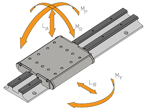
Standard bearing equations will yield inaccurate data for wheels that are axially loaded because the axial load is not uniform on the wheel. Axial loading will in fact result in a moment load on the wheel, causing uneven loading on the ball bearings. That’s in contrast with a thrust bearing in which the load is distributed equally on all the balls.
The wheel can accept higher moment loads by increasing the radial preload, although this makes for a much higher wear rate.
Systems with guide wheel equipped wheel plates can be subjected to both linear and moment loading conditions. Moment loads on a wheel plate are forces that cause torque loading around the wheel plate’s coordinate axes.
Considerations for linear guide-wheel life: Several factors influence the service life of a guide wheel system. A simple method exists to estimate the load-life relationship for a specific guide wheel system under defined loading conditions. This methodology accounts for the size of the bearing elements, relative spacing, and orientation, location and magnitude of the load. The equation is based on clean and well-lubricated track conditions. For applications where lubrication is prohibitive, a derating factor must be applied.
Note that secondary considerations such as maximum velocity, acceleration rates, duty cycle, stroke length, environmental conditions, the presence of shock or vibration, and extreme temperature ranges can all impact service life to varying degrees. So this sizing method is considered only as a guideline for guide wheel components and assemblies.
Load-life equation for sizing and selecting: The load-life estimation requires a basic understanding of the principles of statics, the ability to work with free-body diagrams, and the capacity to resolve externally applied forces on a wheel plate into the radial and axial reaction forces at each guide wheel in the design.

The life of a guide wheel system is limited to the life of the most heavily loaded bearing in the design.
Step 1: Calculate the resultant radial (FR) and axial (FA) loads reflected to each bearing element in the linear guide design …
All standard considerations involved in statics calculations must be accounted for, including inertial forces, gravitational forces, external forces such as tool pressure, bearing element spacing, and magnitude and direction of the payload. Any external forces that generate a reaction through the wheel/track interface must be considered.
Step 2: Calculate the load factor (LF) for the most heavily loaded bearing …

FA = Resultant axial load on the guide wheel
FA(MAX) = The maximum radial working load capacity of the guide wheel (from table)
FR = Resultant radial load on the guide wheel
FR(MAX ) = The maximum radial working load capacity of the guide wheel (from table)
Step 3: Calculate the life by applying the load factor to the load-life equation …

LF = Load Factor
LC = Live Constant (from table)
AF = Adjustment Factor
Adjustment factor (AF) — Due to varying application load and speed parameters and environmental conditions, an appropriate adjustment factor (AF) must be applied to the life equation. Adjustment factor application conditions include contamination, duty cycle, speed, acceleration, shock and presence or lack of lubrication. Consider one application example for which:
FA = 50 lbf
FR = 200 lbf
Wheel Size = 2
Environment = Moderate shock loading and contamination with intermittent motion
Following the above steps, we know radial (FR) and axial (FA) loads on each wheel …
… so can calculate:
FA = 50 lbf
FA(MAX) = 141 lbf
FR = 200 lbf
FR(MAX) = 596 lbf
LF = 50/141 + 200/596 = 0.69
Life = 3.47 x 10⁶/ (0.69)3 x 0.6 = 6.33 x 106 inches of travel
Note that an adjustment factor (AF) of 0.6 adjusts for environmental influences.
Wheel-plate configurations: How to properly design a wheel plate
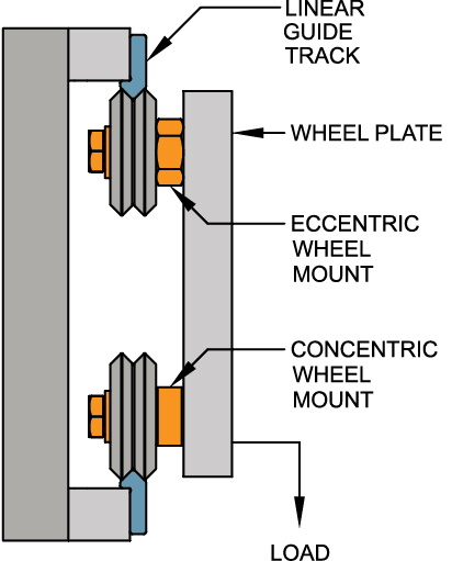
In designing a wheel plate, it’s important to use the right combination of eccentric and concentric guide wheels depending on the configuration. The linear system should always have two concentric wheels while the remaining guide wheels should be eccentric. The eccentric wheels eliminate play (clearance) between the wheels and tracks and allow preloading of all the wheels so that they roll smoothly instead of sliding or skipping on the track. If the wheel plate is loaded in the radial direction, the concentric wheel should support as much of the radial load as possible.
Note that the optimal locations of the eccentric and concentric wheels relative to an applied radial load are dependent on whether the tracks are between or outside of the wheel plate’s two rows of wheels.

Linear guide-wheel bearing preload
Wheel plate preloading creates radial loading between the wheels and tracks that exists when the system is not loaded by another outside force, and serves to eliminate play between the wheel and track.
Preload = Measured wheel plate breakaway force / (# of wheels × Coefficient of friction)
During assembly of the system, the wheel plate should be placed on the tracks, without any load attached, and with the concentric wheels fully tightened and the eccentric wheels tightened just sufficiently to permit adjustment.
Preload adjustment is accomplished by gradually rotating the eccentric wheel bushing(s) until the tracks are held captive by the two sets of wheels on each side of the wheel plate, with no apparent clearance between the tracks and wheels and very light preload. Once this is accomplished, fasten the eccentric wheel(s) so that they hold their positions.
Next, check each wheel for correct preload by rotating the wheel with your fingers, while holding the track stationary. The wheel should skid against the track with a small amount of resistance, but should still turn without much difficulty. If rotation is not possible, the preload should be reduced accordingly by readjusting the eccentric wheel(s).
Caution must be used when applying preload because too much preload on the wheels can cause premature failure. The rated radial load should never be exceeded by the preload and subsequent radial loads applied to the wheel when in service. Note that preloading cannot compensate for large variations in track parallelism tolerances which can occur in long travel length systems.
By Leslie Lui, Mechanical Design Engineer | Bishop-Wisecarver • Pittsburg, Cal. || Reprint info >>
Complete linear guides: 2018 offerings
Bishop-Wisecarver invented and patented DualVee Motion Technology more than 40 years ago to provide a setup for harsh environment applications where existing technologies were ineffective. DualVee also proved excellent for long length, smooth motion and low noise requirements.
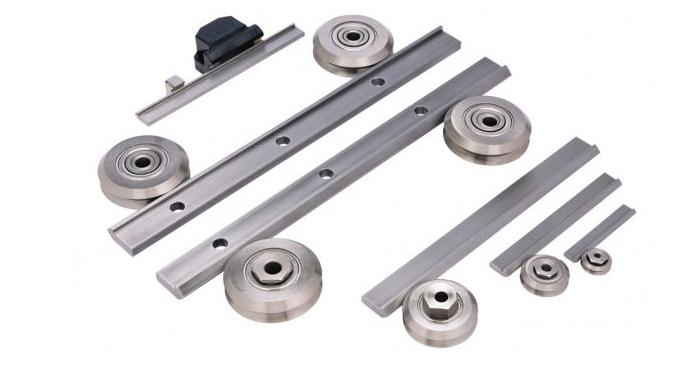
Today, Bishop-Wisecarver remains the saw expert and the most trusted name in guide wheel technology with the widest range of guide wheel based linear motion products in the world. Benefits of guide wheel technology include:
- Ability to withstand harsh environments as well as high and low temperature
- Long lengths available
- Quiet and smooth low-friction motion; speeds to 5.5 m/sec
- Acceleration up to 5 g
- Cleanroom options
- Ease of assembly and low-cost installation; low maintenance
Download Bishop-Wisecarver catalogs from Canadian distributor Electromate or visit bwc.com.




Leave a Reply
You must be logged in to post a comment.