
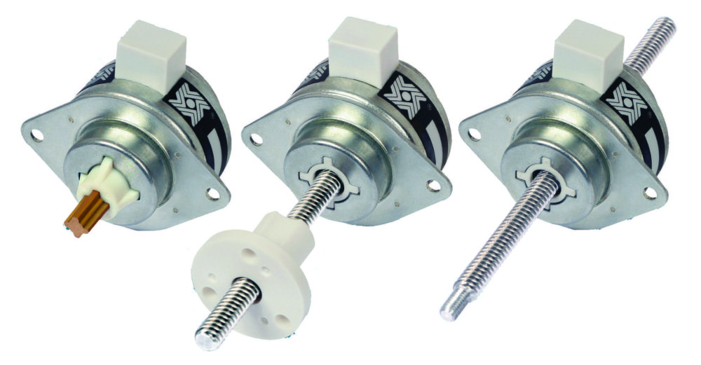
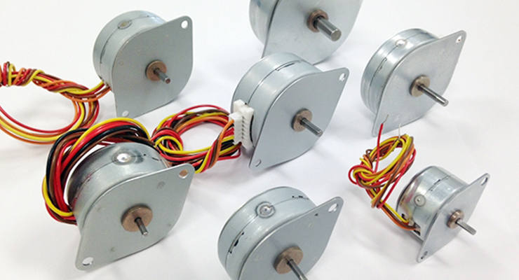
Can-stack linear actuators are one type of stepper-motor design that converts rotary to linear motion with a built-in leadscrew. The linear actuators incorporate can-stack motors — sometimes called claw-tooth step motors, tin-can stepper motors, or claw-pole motors — leverage low-cost construction with punched sheet-metal parts that form toothed (or clawed) cups surrounding bobbin coils.
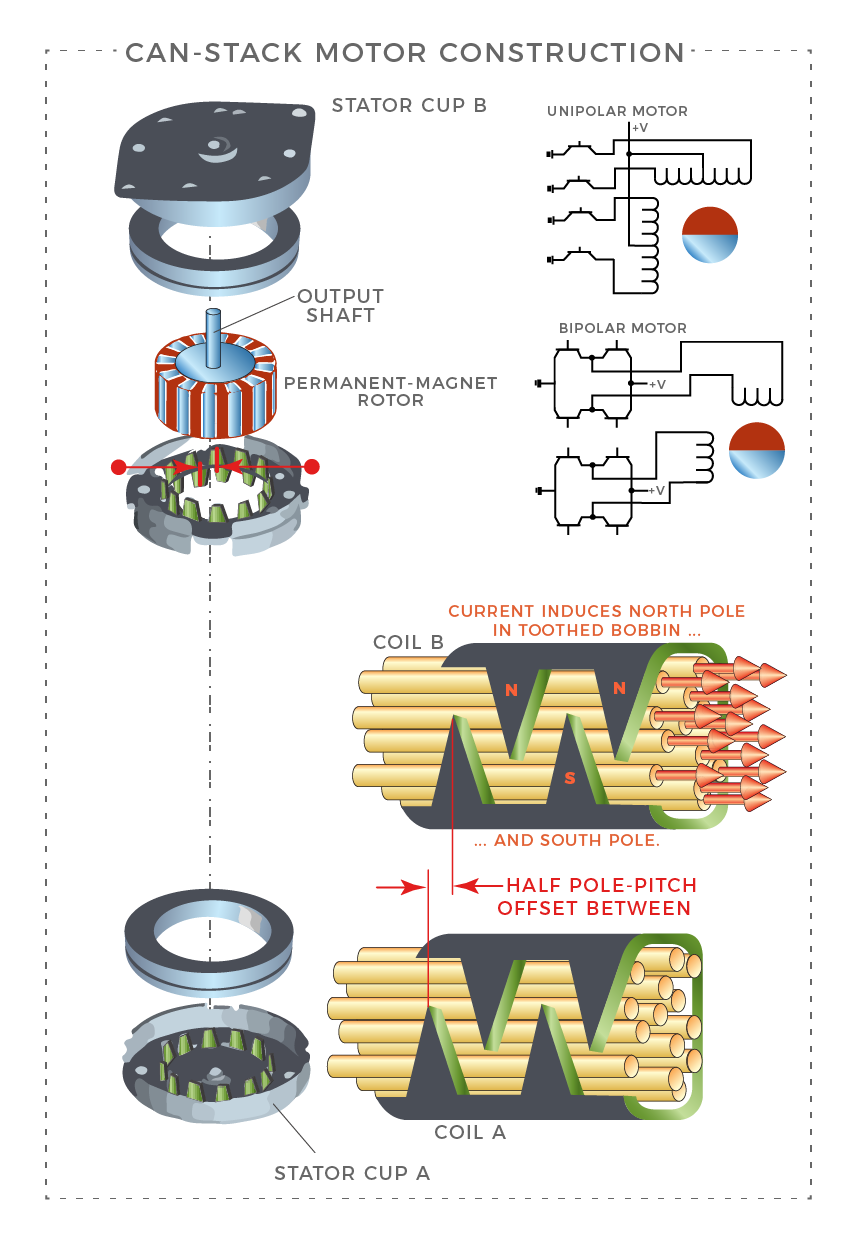
Common are twin-stator assemblies that deliver two phases for indexed output. Here, the two stators’ claws (teeth) are offset by one-half the pole pitch — 360° ÷ number of teeth ÷ 2. The rotor has an array of permanent magnets and the same number of pole pairs as the coils.
In fact, can-stack motors have become quite common over the last 30 years — especially with the proliferation of higher-volume lower-cost applications in consumer-grade designs and small appliances.
This piece is an expansion of the topic What are can stack linear actuators? covered by Danielle Collins. Read the original here.
As we’ll explore, the linear-actuator variation of can-stack stepper motors are suitable for industrial applications (as in medical diagnostic equipment and pumps) as well as consumer devices (such as printers and copiers) and military-grade radar and antenna requiring precise linear actuation.
Common ways to drive can-stack motors
As with all stepper motors, can-stack motors run off electrical-pulse trains to output mechanical movement. Their output shafts turn in discrete increments fed properly sequenced electrical input. As with other stepper designs, can-stack motors usually run open loop as well.
Consider the common design of two cans (stators). These can induce four discrete positions for every pole pitch. Step angles for can-stack motors are 18° to 3.6° — or 20 to 100 steps per revolution. However, the most common step angles are 7.5° to 15.0° for each energizing pulse. Finer mechanical resolution makes for finer motion output.
Can-stack motors exhibit step error (expresses as plus-minus some angle — for example, ±0.3°) but error never accumulates over steps … so the motor output is suitable for positioning. Many designs run in full, half, or micro-stepping modes.
Consider the common variation with 24 poles in each coil or phase. With 24 poles around 360° the pitch between poles on one stator is 15° — but because half a pole pitch offsets two stators, there are 7.5° between stator poles. That means when the drive energizes stators individually, the motor rotates 7.5° each step. Phase-energization sequence dictates the rotational direction while the pulse frequency dictates rpm. Input pulses dictate rotation length.
What to know about can-stack motor variations
Design variations for can-stack motors abound. However, a typical can-stack motor’s bobbin-wound coils are either unipolar or (more common in today’s setups) bipolar to let design engineers pick the most suitable motor for the required electrical input and motor output.
Unipolar motors have two windings for each coil but only use them one at a time. Once the most common, unipolar setups supply unidirectional current into two-phase bifilar windings. Remember here that a bifilar winding is one consisting of two closely spaced parallel windings. Because each motor coil only has one polarity (to act as a north or south electromagnet) they must switch on and off to prompt output motion. This simplifies drive electronics — and helps unipolar motors excel in high-speed applications, because they don’t rely on full winding-current decay before energizing the opposite polarity.
Contrast this with bipolar motors that only have one winding per coil and switch polarity to prompt output motion. Here, current decay must be complete to let polarity switch and motion output. Drive electronics for bipolar motors are slightly more complicated than those for unipolar motors, but they work better on slower axes and high-torque applications.
Linear actuators based on can-stack motors
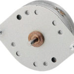
Manufacturers make linear actuators from can-stack stepper motors by threading the motor rotor and assembling it with a leadscrew so the latter extends and retracts as the motor turns. Some manufacturers produce can-stack linear actuators with sintered bronze bearings for support. Ball bearings with lubrication containment (for extended operation without service) are another option where needed to extend machine life.
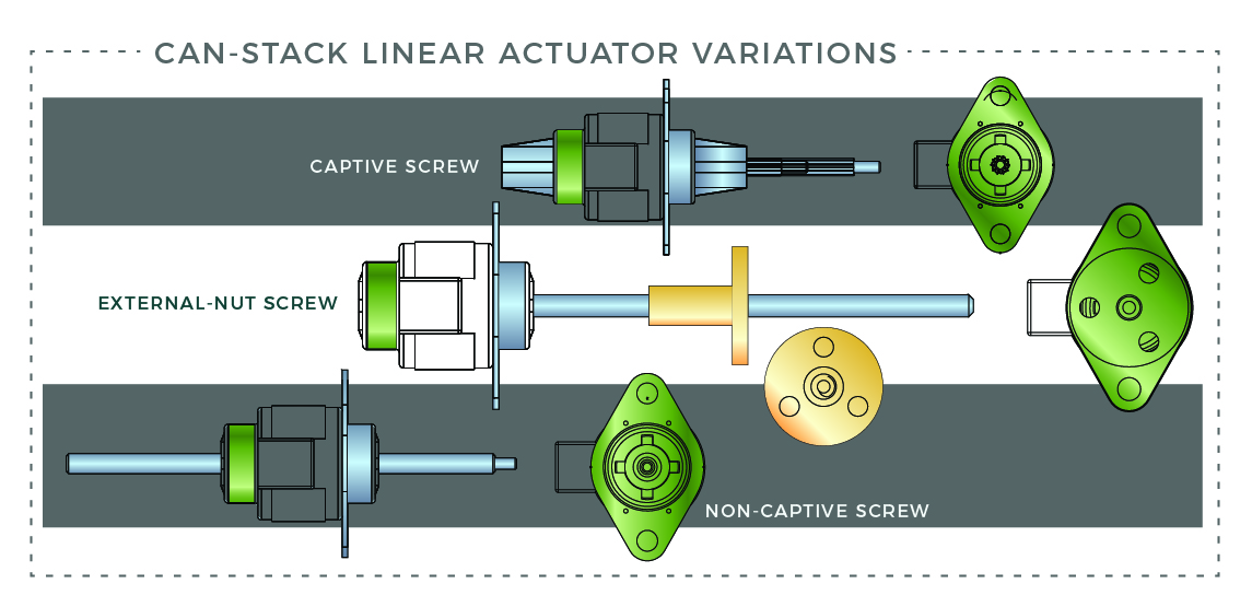
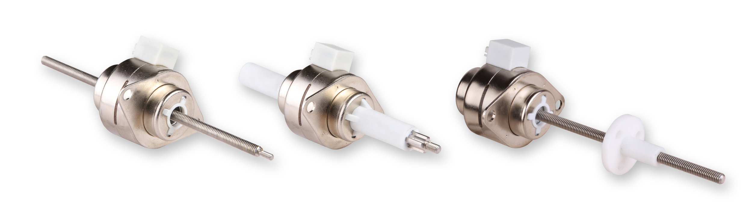
No matter the features or output-shaft format, three common designs exist for can-stack linear actuators:
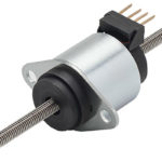
1. Captive linear actuators have screws held by a device (either internal or external to the motor) that prevents rotation. One can recognize a captive linear actuator by how the output shaft extends and retracts into the actuator body. Common applications include those in small dispensing machinery and miniature industrial valves.
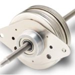
2. Non-captive actuators have screws that rotate with the motor — so rotation is typically prevented by the application’s inherent design. Non-captive linear actuators excel in long-stroke applications. Some applications include position-ing systems for antenna and laboratory dispensing equipment.
3. Traveling-nut actuators include screws that don’t extend and retract. Instead, the nut (external to the motor) travels along the screw as motor and screw turn together. Some applications for traveling-nut can-stack actuators include collaborative-robot end-effectors; printers; and automated designs for clinical diagnostics.
Most can-stack linear actuators also leverage detent torque to hold position even if power is cut. The rotor’s permanent magnets attract to the stator poles (in this case, can-stack claws) even without power to the stator windings. Overcoming detent torque requires motor power at a level proportional to rpm. A faster-turning motor sees more degradation of torque output by detent torque … as the latter reduces both ideal power and torque output. On the other hand, detent torque is useful when stopping. That’s because detent torque (and friction in rotating components) partially counters the moving motor’s momentum. So detent torque (usually about 5 to 20% of holding torque) helps can-stack motors stop more quickly.
Practical can-stack actuator considerations
While can-stack linear actuators are indispensable for myriad cost-effective motion designs, they do impose some special drive considerations. For example, their main drawback may be inefficiency — down to 25% in some cases. First, the airgap in a can-stack motor is several thousandths of an inch, which makes for slightly less efficient rotor-stator magnetic coupling than competitive technologies. Second, the stator assembly relies on low-carbon steel parts for the clawed cups for operation — again, slightly less efficient than the construction of other motors.
For many designs, can-stack inefficiency isn’t an issue. However, if a design occasionally runs off battery power — not an uncommon occurrence in especially small designs — a better alternative may be linear actuators based on hybrid stepper-motor designs. Consult with manufacturers when making this determination.
In addition, the geometry of the linear actuator is such that load may cantilever on the screw in certain modes of operation. On axes where this is a common occurrence or where the screw must remain in an extended or retracted position, additional design work may be necessary to ensure reliable actuator operation.
All this said, can-stack linear actuators can often meet small application demands for speed, force, and resolution. For the latter design objective, some actuators even include suitably cost-effective feedback in the form of proximity-sensor ICs based on Hall-effect operation. Permanent magnets affix to the internal screw end; as the screw extends and retracts, the magnet advances towards and moves away from the stationary sensor pickup. Such non-contact feedback is also suitably compact for the tight spaces into which can-stack linear actuators are often applied.


Leave a Reply
You must be logged in to post a comment.