
Ball and lead screw assemblies consist of three main components: the screw shaft, the ball nut, and the end support bearings. More than just an accessory, end support bearings have a significant influence on the rigidity, maximum speed and buckling load of screw assemblies.
There are two primary types of support that can be implemented for a ball or lead screw end: simple (also referred to as floating) and fixed. Simple support is achieved with a single ball bearing, which provides support against radial loads. Fixed support is achieved with an angular contact thrust bearing, which counteracts both axial and radial forces on the screw.
A third type of support can be achieved when two single ball bearings are mounted with a space between them. This is often referred to as “double simple” or “double floating” support. The use of two simple bearings, rather than one, allows the screw to obtain higher speeds than a standard floating end. But unlike a fixed bearing support, two simple bearings also allow for some axial movement of the screw, in the case of expansion or contraction due to temperature fluctuations.
When no bearing support is applied to the end of a screw shaft, that end is considered “free.”
End fixity conditions
There are four combinations of end fixity: fixed-fixed, fixed-floating, floating-floating, and fixed-free. Each one supplies a different level of rigidity to the screw assembly and is suitable for particular application and assembly requirements.
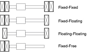
Fixed-fixed: This is the most rigid form of end fixity. It provides the highest speed capability and support for buckling loads, but it doesn’t allow any axial movement of the screw in the case of thermal expansion. Screws that are placed in tension, such as those used with driven ball nuts, use fixed-fixed bearing supports.
Fixed-floating (aka fixed-simple): This is probably the most common type of end fixity. It provides both axial and radial support for the screw and contributes to high critical speeds and buckling loads, while still allowing for thermal expansion of the screw shaft.
Floating-floating (aka simple-simple): This bearing arrangement has the benefit of easy mounting while still providing radial support for the screw. It also allows for compliance in the axial direction.
Fixed-free: Leaving one end of the screw assembly “free” (without bearing support) simplifies mounting, but greatly reduces the critical speed and buckling load capabilities. Thus, fixed-free support is used only for applications with short screw lengths and slow speeds.
End fixity and screw performance
Two parameters of ball screw performance, critical speed and buckling load, are directly proportional to a factor based on the end bearing arrangement. This end bearing factor is highest for the most rigid support (fixed-fixed) and lowest for the least rigid arrangement (fixed-free).
Buckling load and critical speed are also inversely proportional to the square of the unsupported screw length. Therefore, using fixed support on one or both screw ends provides a secondary benefit, in that it reduces the unsupported length of the screw, reducing the denominator for both buckling load and critical speed equations, and providing higher values for both.
Critical Speed Equation
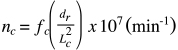
nc = critical speed (rpm)
fc = factor based on end support bearings
dr = root diameter of screw (mm)
Lc = unsupported length of screw (mm)
Buckling Load Equation

Fb = maximum compressive load (N)
fb = factor based on end support bearings
dr = root diameter of screw (mm)
Lc = unsupported length of screw (mm)
Determining the type of end fixity required by the application prior to ordering a ball or lead screw assembly allows the manufacturer to machine the screw ends accordingly. Although it is feasible for the user, OEM, or other outside machine shop to machine the ends after the screw is delivered, the screw manufacturer typically has better capabilities to ensure that suitable tolerances are achieved for concentricity, axial run-out, and radial run-out of the bearing surfaces.

Leave a Reply
You must be logged in to post a comment.