
The manufacture and testing of semiconductors involves the competing requirements of nanometer positioning and high throughput. Here, the right encoder can help motion designs deliver on both counts.
By HEIDENHAIN CORPORATION staff engineers
Semiconductor manufacturing and testing equipment can have the best motion-control bandwidth, artificial intelligence capabilities, and optics in the world, but none of that matters if the processes fail to reach nanometer-level positioning precision without degrading throughput. In fact, that is the main challenge of semiconductor testing especially — that the design objective of getting precise measurements is in direct conflict with the design objective of making those probes as quickly as possible.
Of course, motion drive capabilities and structural integrity are key to the successful operation of equipment for semiconductor manufacture. Just as important as maximum motion-system axis speed is short settling times — especially if a process involves measuring precise points on a wafer at each stop. Here, suitable encoder performance is essential to meeting the challenging combination of speed, accuracy, and stability for such advanced processes.

Choosing the right linear-motion feedback solution
To meet a machine’s requirements, design engineers currently have a variety of motion feedback solutions from which to choose for both linear and rotary movements. Despite the growing array of new feedback technologies, the parameters that ultimately dictate the best encoder choice are similar for all solution types. Here are some points to consider when deciding on the right product.
1. What environmental conditions must the encoder endure? Will the machine axis in question be subject to vibration, vacuum conditions, or extreme temperatures?
2. What level of feedback and positioning accuracy will the machine axis require?
3. At what speed will this accuracy be reached?
4. How much interpolation error can the involved machine operation allow?
5. Are there any mechanical restrictions that may restrict the available space or method of encoder mounting?
Check the axis requirements (and find suitable solutions)
Defining machine design parameters effectively narrows down the logical options for encoder feedback. An early choice may be the type of encoder — whether mechanical, optical, magnetic, or induction. For example, if a process takes place in a vacuum and is very space restricted, then the suitable choices for an encoder will be narrowed down to products having one or more of the following features:
• A short and squat scanning head
• Adhesive-based or press-fit scale installation
• A scale consisting of two thin metal layers (one with the graduation imprinted) for forgiving attachment to some machine section subject to temperature fluctuations
In contrast, high-precision equipment operating in vacuum settings (such as that for photomask fabrication) may necessitate a high-accuracy encoder exhibiting minimal outgassing. From there it’s a matter of referencing all remaining catalog specifications to make the final encoder choice.

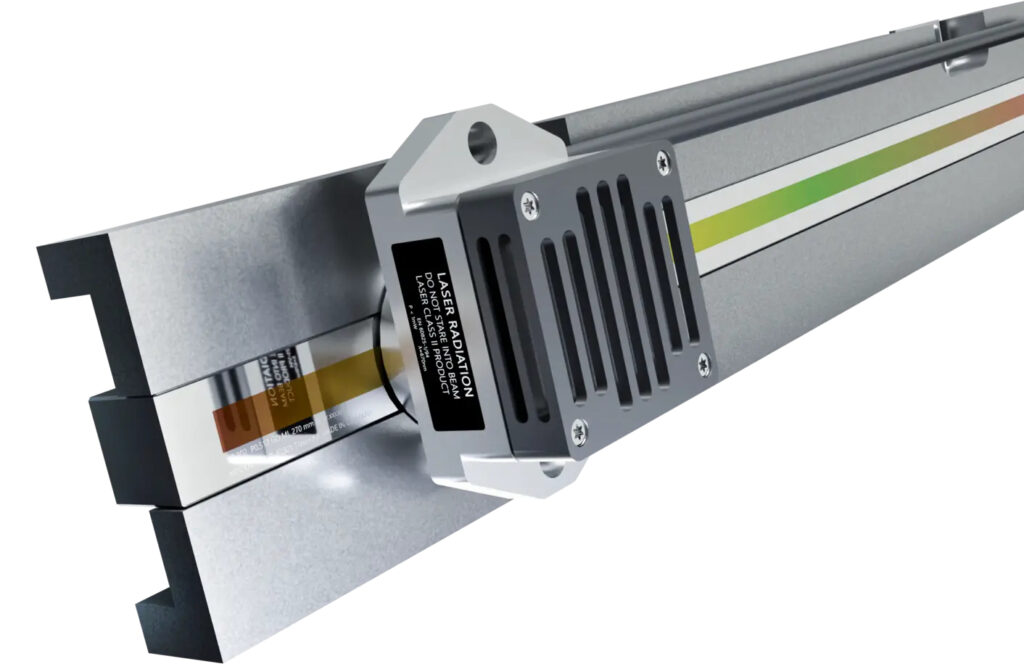
Another key encoder element (for both linear and angle encoders) is the measuring standard — or the scale-tape graduation. A scale’s line count gets a lot of attention, but how these lines are created (applied to the scale) at defined intervals is also important. The design of the encoder graduation determines both upfront performance capabilities and maintaining consistent quality over time. That’s why some encoder suppliers have developed their own methods of scale-tape manufacture. That in turn has led to the availability of scale-tape graduation designs having 3D structures with very high edge definition.
Encoders manufactured this way have a high resistance to contamination that can otherwise disrupt front and backend semiconductor work. The structures have a very low height … and that in turn leaves practically no surface for dust, dirt, or liquid to accumulate.

Testing encoders for nanometer positioning
The semiconductor industry is unforgiving of motion components exhibiting any unreliability. Specified encoders are expected to be thoroughly tested and capable of meeting very specific standards. Most manufacturer catalogs are loaded with extensive test descriptions, results, and verified specifications to give design engineers confidence that each component will perform to listed values.
Case in point: Some linear-encoder manufacturers test intervals on their linear-encoder scales so OEMs and end users can more accurately anticipate their performance in the field. In this interval-testing process, the manufacturer quality team first defines the interval width for which the accuracy is to be stated. Then the team continually measures the encoder scale with the chosen interval width over its entire measuring length … with the width consisting of very small and well-defined measuring steps.
Finally, uncompensated baseline errors over each interval width are evaluated. The worst value (in other words, the largest baseline error detected over all measured intervals) is then provided as the maximum baseline-error value on that linear encoder.
Such verification of encoder performance, proprietary measuring standards, and commitment to encoder R&D mean that the evolution of encoder technologies will continue unabated — which will be especially useful to the semiconductor industry.
HEIDENHAIN | heidenhain.us

Leave a Reply
You must be logged in to post a comment.