• Skip to primary navigation
  • Skip to main content
  • Skip to primary sidebar
  • Skip to footer
  • Advertise
  • Subscribe

Linear Motion Tips

Covering Linear Motion Systems, Components and Linear Motion Resources

  • News
    • Editor’s blog
    • Industry news
    • Motion Casebook
  • Applications
  • Slides + guides
    • Ball + roller guides
    • Track roller (cam + wheel) guides
    • Crossed-roller slides
    • Linear bearings
    • Plastic + composite guides
  • Drives
    • Ball + lead + roller screws
    • Belt + chain drives for linear
    • Rack + pinion sets
  • Actuators
    • Ball + leadscrew driven
    • Belt + chain driven
    • Linear motors
    • Mini + piezo + voice coil
    • Rack + pinion driven
    • Rigid-chain actuators
  • Encoders + sensors (linear) + I/O
  • Stages + gantries
  • Resources
    • Suppliers
    • Video

Contact angle: What is it and how does it affect linear bearing performance?

★ By Danielle Collins Leave a Comment

In profiled rail linear guides that use balls or rollers, the geometry and arrangement of the bearing raceways play a significant role in the bearing’s load capacity, friction, rigidity, and ability to withstand errors in mounting. But there’s another aspect of a bearing’s design that also plays a role in its load capacity and rigidity — the contact angle.

ISO contact angle
Image credit: ISO

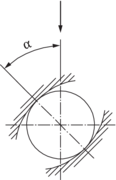
The ISO 14278 standard for linear motion rolling bearings defines the nominal contact angle as:

The angle between the direction of load on the linear bearing and the nominal line of action of the resultant of the forces transmitted by a bearing raceway member to a rolling element

45 degree contact angles for equal load capacity

Linear guides that use Gothic arch geometry — including miniature profiled rails and most roller bearing guides — have four-points of contact between the ball and the raceway, which results in a contact angle of 45 degrees.
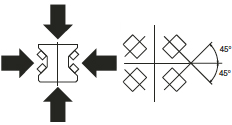
linear bearing contact angle
Bearings that use a 45 degree contact angle have equal load capacities in all four primary directions.
Image credit: NSK

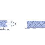
The benefit of the 45 degree angle is that it provides the bearing with equal load capacity in all four primary directions — radial (downward and lift-off) and lateral (side) loading. This means the guide can be used in any orientation without the need to de-rate the load capacity.

linear bearing contact angle
Top: When the contact angle is 45 degrees for all rows of balls, the load capacity is the same in all four directions.
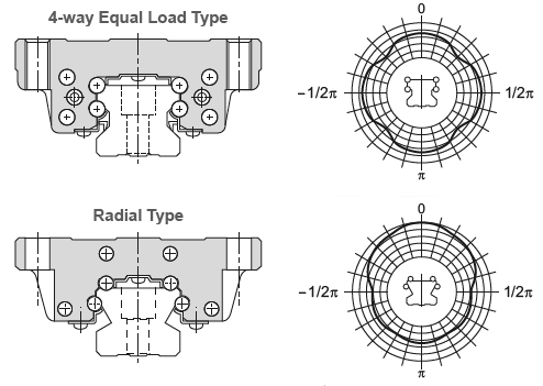
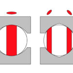
Bottom: When the contact angle is larger for the top rows of balls, the load capacity is higher in the radial direction but lower in the reverse radial and lateral directions.
Image credit: THK

Higher contact angles for better radial load capacity

Linear guides that use circular arc or offset Gothic arch geometry, on the other hand, can be designed with varying contact angles to produce higher load ratings in one direction, although at the sacrifice of load capacities in the other direction.

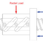
For example, one circular arc design uses a contact angle of 90 degrees on the top rows of balls, with a smaller angle of 30 degrees on the lower rows of balls. This gives the bearing extremely high load capacity for radial (downward) loads — which is the primary loading direction in many applications — since the load is being transferred from the top rows of balls directly downward into their raceways. It also gives the bearing very high rigidity (low deflection) when radial loads are applied. The tradeoff for higher load capacity and rigidity in the radial direction is lower load capacity and rigidity in the reverse radial and lateral directions.
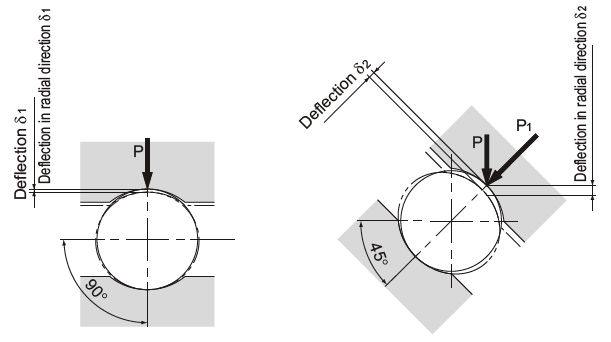
contact angle and deflection
The closer the contact angle is to 90 degrees, the lower the deflection in the radial direction.
Image credit: THK

Another design, based on the offset Gothic arch geometry, uses a 50 degree contact angle for all four rows of balls. This provides higher load capacities in both the radial and reverse radial directions, but lower load capacity in the lateral direction.
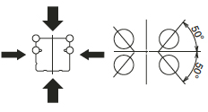
linear bearing contact angle
This bearing uses a 50 degree contact angle for all four rows of balls, giving it higher load capacities in the radial and reverse radial directions, but lower capacity in the lateral direction.
Image credit: NSK

You might also like

Filed Under: Ball + roller guides, Crossed-roller slides, FAQs + basics, Featured, Linear bearings

Reader Interactions

Leave a Reply

You must be logged in to post a comment.

Primary Sidebar

LEARNING CENTER

Design World Learning Center
“lmt
EXPAND YOUR KNOWLEDGE AND STAY CONNECTED
Get the latest info on technologies, tools and strategies for Design Engineering Professionals.
“linear

RSS Motion Control Tips

  • igus one-piece energy chain targets compact cable routing
  • EtherCAT meets CRA Level 2, higher-security options in work
  • Elmo debuts new Titanium line and Platinum servo drives at SPS 2025
  • AutomationDirect adds new soft starters and smart motor starters
  • Vert-X 26-series angle sensors are robust and accurate

RSS Featured White Papers

  • Robotic Automation is Indispensable for the Logistics Industry’s Continued Growth and Success
  • Reliable Linear Motion For Packaging Machines
  • Technical Brief – “Understanding the Extensive Benefits of Total Linear Positioning Systems.”

Footer

Linear Motion Tips

Design World Network

Design World Online
The Robot Report
Coupling Tips
Motion Control Tips
Bearing Tips
Fastener Engineering
Wire and Cable Tips

Linear Motion Tips

Subscribe to our newsletter
Advertise with us
Contact us
About us

Copyright © 2026 · WTWH Media LLC and its licensors. All rights reserved.
The material on this site may not be reproduced, distributed, transmitted, cached or otherwise used, except with the prior written permission of WTWH Media.

Privacy Policy