
by Brian Kienlen, Master Electronic Operations Director, Entertrainment Junction, West Chester, Ohio
With over 200 trains, 100 individual tracks and more than 1,200 cars, Entertrainment Junction’s complex control system keeps model trains running on time.
What does it take to control the world’s largest indoor train display with over 200 G-Scale model trains and more than 100 individual tracks laid down over two miles? Start with a 25,000 square foot facility, and add six AutomationDirect Terminator Series PLCs with discrete and analog I/O, each one responsible for operating an area of the building. Network the PLCs and add programming to allow multiple trains to operate together, some sharing the same tracks and sidings—and you have a complex yet easy to operate control system for a model train hobbyist’s dream come true.

Large-scale simulates real-world
Entertrainment Junction uses G-Scale model trains, with the 1:24 scale representing the ratio of the model to real-life size. The G-scale model train is the largest of the mass-produced trains, with one inch on the model equating to about two feet in real life. Thus, a 40-foot boxcar would be around a foot and half on a model railroad, or about the size of a loaf of bread. These big, burly model trains operate on 2-rail track, use dc power, and can run indoors or outdoors.
Currently, there are over 110 trains operating on over 200 individual main lines with electrically isolated and segregated blocks. This allows for multiple locomotives to be controlled independently within a single track line. In some cases, a single line will have up to seven trains operating at the same time.
Similar to real-world trains, the track block system used on the model display ensures locomotives will stop and wait until the block ahead is clear. Since no two trains run at exactly the same velocities, blocks are required so that one can stop and wait before advancing to the next block. Without segregated blocks, trains would eventually catch up to each other, ultimately causing collisions and often derailments.
Switches are controlled by a small 12 Vdc rotary motor that is always either pushing or pulling against the switch through a connecting rod. A relay controls the polarity of the voltage being delivered to the dc motor, thus controlling the direction of rotation. The continual applied pressure from the connecting rod to the switch allows for secure positioning, eliminating derailments from unsecured rails within the switch.
Upgrading the control system
Local volunteers and enthusiasts designed and manufactured the original control system by hand. The custom printed circuit boards with resistors, diodes, transistors, capacitors and other electronic components were all soldered and assembled on site. Each track had its own control panel containing all the parts and pieces making up the control system.
A computer ran the original circa 1970s C programming language, written before C++ was even developed. 45 of the control panels were originally made, and more were eventually added to accommodate growth. Power to the trains was regulated with a single capacitor and several transistors.
After running well for six years, maintenance on the original control system became problematic. When parts wore out or broke, they had to be repaired by hand. Replacement parts weren’t available for much of the hardware or components. A more flexible control system was needed for this large distributed control application, and AutomationDirect was selected as the primary supplier.
The new control system is a 100% retrofit, completely replacing the older control hardware with AutomationDirect components. Up to eight AutomationDirect Do-more PLCs are planned, each one using 55 discrete 16-point input modules, 40 discrete 16-point output modules, and 30 analog 16-point 0-10 Vdc input and output modules.

The control system simultaneously monitors over 850 magnetic read sensors and control buttons, over 640 12 Vdc relays and indicator lamps, and over 500 individually controlled blocks. It also provides voltage control for the engines. Other control functions include bridge up/down, traffic signals, switches, speed changes, stops and starts.
The new control system is responsible for controlling multiple trains on multiple tracks simultaneously. In most cases, multiple trains are operating together on the same tracks, with state logic programming coordinating the locations and speeds of each train. The old system had a single control panel for each train, operating independently from the rest of the layout. The new configuration ties every train and track together into one main control system, which allows for much more diversity on how the trains can operate, both individually and in relation to each other.
The old system controlled the voltage feeding the track using analog components, including a combination of NPN transistors, optical amplifiers, resistors and capacitors.
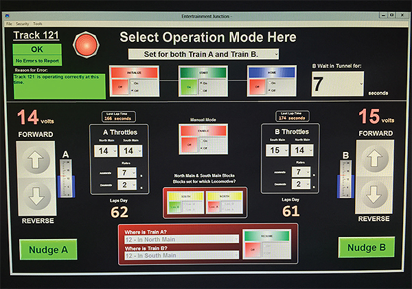
The new control system controls all analog voltages through the PLCs. Each PLC has a built-in web server, allowing speed control voltages and other values to be set using a web thin client running on an iPad or Surface tablet. Acceleration and deceleration rates can also be adjusted, along with many other parameters. The web thin client also provides a comprehensive view of train operation, along with the ability to drill down to more detailed levels as required by the operator. HMI software access through a wireless tablet lets the user be out and about in the layout and watching the results based on the user input, rather than being blind behind the scenes as with the original control system.
Keeping an eye on the train schedule
While running over 110 trains, there is a high demand for retrieving information. For data acquisition, the PLCs count laps for each train and records fastest lap time, slowest lap time, average lap time, voltage input versus voltage output and the locations of the trains.
Trend views inside the Do-more programming software detects voltage spikes and dips, which lets the staff know when a track needs to be cleaned, or if a train is drawing more current than it should. Voltage spikes on a graph indicate points along the track where the locomotive briefly lost continuity with the rail, indicating dirty track or wheels. On the other hand, voltage dips indicate heavy resistive loads, perhaps due to a stock car’s wheels shorting out while in motion, or bad motor brushes on a locomotive engine.
The PLC is programmed to automatically recognize voltage changes and alert staff through email if a track needs cleaning or if there are issues with rolling stock. In extreme cases, the PLC will automatically shut down an operating line if a voltage dip exceeds a threshold over a set period of time.
Controlling a speeding train
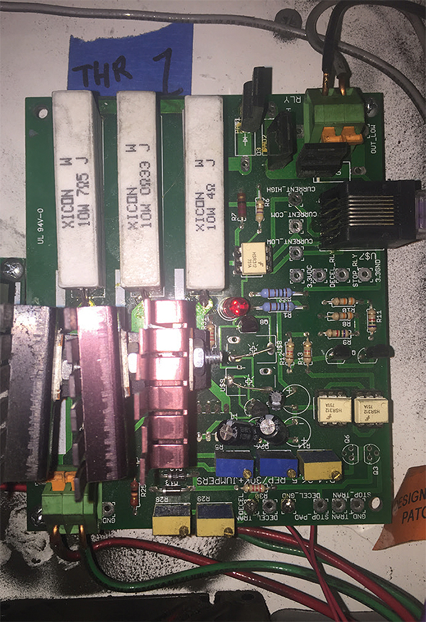
Analog signals are used to control the voltages supplied to the rails on the tracks, which then power the locomotives and other third rail train equipment. It’s important that trains accelerate and decelerate at certain rates to prevent damaging the locomotives. The PLC’s analog voltage output modules are rated 0-10 Vdc, while the train’s operating voltage is between 0 and 24 Vdc, with an average current load of 2 to 5 A.
Because the analog output module isn’t designed to handle such a load, a custom-designed amplifier board converts the low-level 0 to 10 Vdc output to an amplified, high current 0 to 24 Vdc output. This amplified voltage then feeds a 40-A power transistor that drives power to the locomotives. The power transistor is doing the work of supplying the current to the locomotive, with the PLC simply providing a control voltage that regulates the transistor’s output.
The PLCs monitor the track’s segment block voltage. Using Ohm’s law and the fact that a dc motor running with a steady load will look resistive to a steady-state dc supply, train engine operation can be effectively monitored. The resistance of the locomotive can be determined, providing a good representation of the power drawn on the track.
This power draw information gives an indication of where there are continuity issues such as a dirty track. A lower voltage return indicates a higher resistive load. A threshold is set within the control system, and any reading higher or lower than the threshold will cause the train to shut down and send a text message to an operator’s phone for immediate investigation.
The control system monitors voltages continuously to catch overload issues, often before the circuit breaker trips. Rolling stock cars have axles that often wear and cause shorts, and inputs to the PLC’s 0 to 10 Vdc analog feedback modules detect when that behavior is present and stops the train.
PEERLINK for Ethernet was used as the communication network, allowing all the PLCs to talk to each other, either directly or through the SCADA system. The PEERLINK instruction makes it simple to share data over Ethernet between multiple Do-more CPUs, with transparent data sharing using peer logic variables in a designated memory area.

Train program on schedule
State logic programming is the primary backbone for all the programs in this model train system. On the tracks themselves, there are magnetic sensors located throughout the entire track line, and some tracks may have up to 36 sensors. A rare-earth magnet is mounted on both the front and the rear of each train to activate these sensors. Each time a magnetic sensor is hit, the state of that particular train is changed.
From there, the programming possibilities are almost endless. The system can detect if a train is broken in two, simply based on if a magnetic sensor is activated while the train is under a given state assignment.
If a train hits a sensor under incorrect state parameters, the system will shut down that train, preventing operating malfunctions or potential train collisions. A message will then be sent to the SCADA system describing the error and the location of the train. Usually within seconds, the problem is identified and a plan is established to correct the mishap.
Entertrainment Junction
www.EntertrainmentJunction.com
AutomationDirect
www.automationdirect.com

Teams like your’s have time and again proved that hobbyists have been the main sources of technology development.Hope you have enough funds flow for this inspiring work to go ahead. Great work.