 By Lisa Eitel • Robot-positioning tracks can add flexibility to manufacturing spaces, but must be fast, accurate, and safe to be truly useful. Here we take a look at drives that deliver.
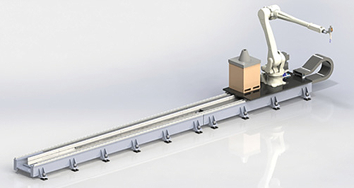
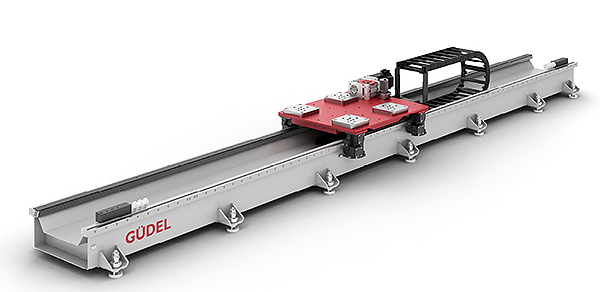
Robot positioning systems are long tracks in warehouse, aerospace, and automotive facilities to let one robot perform multiple tasks. Also called robot-transfer units or RTUs or 7th-axis systems, these motion designs are increasingly common for assembly, large-scale welding, and warehousing.
In contrast with typical setups in which a robot bolts to a floor, RTUs move robots through work-cells and factories and shuttle them between stations. The best setups for RTUs are those just being built or ones where processes and related machines can be put in a straight row. Where RTUs move six-axis robots, the linear tracks are also sometimes called the seventh axis (or less commonly, when the robot itself has seven degrees of freedom, the eighth axis). When these tracks are part of a frame, including frames from which the robot hangs, they’re gantries.
No matter the robot or track morphology, the point of the extra axis is to add translational motion. This either extends the work envelope or lets a robot transport work-pieces or tools. In some arrangements, the former lets a robot tend multiple machines or pick pallets from rows, or machine very large components. For the latter, common applications are packing, welding, plasma-arc cutting, and other mechanical tasks.
Here we focus on drive options for RTUs. However, note that engineers must also decide between an array of guides and bearings (usually in the form of cam followers or profile guides).

Design and drive options for RTUs abound
Though some gantries include framing to invert robots and suspend them for better access into machines from above, RTUs that bolt to the floor and orient the robot upright are most common. These RTUs have higher payloads on average, carrying robot arms and grabbed loads weighing thousands of pounds.
Engineers can buy pre-engineered RTUs or build RTUs in-house using motion-system expertise. The simplest are linear-track pairs that bear platforms to which the robot bolts. However, many OEMs enlist dedicated integrators for situations where robots on RTUs will perform high-precision jobs—for example, a cutting task (where the design must synchronize the articulation of multiple axes) or moving castings through various machine tools for processing.
The biggest challenge to engineering robot-transfer units is programming them to synchronize with the articulation of the robot arms they carry. The second-biggest challenge is getting RTUs to maintain accurate linear motion over many meters.
Meeting physical requirements for long strokes
Sometimes speed is the overriding RTU design objective. That’s especially true when RTUs take robots over a couple hundred feet or even more in specialty setups. High speed in the context of moving robots—sometimes arms weighing thousands of pounds plus their payloads—is relative. However, some RTUs can move at more than 10 ft/sec with acceleration to one g.
But often, accuracy is the overriding RTU design objective. Consider an application where a robot helps a cooperative work-cell with machining, for example. Here, speediness and the extension of the robot work envelope are only useful if surrounding framework can hold accuracy tight. Such designs often need accuracy to 0.02 mm and positioning repeatability to 0.2 mm or so during track movements.

In contrast, if an application uses a robot arm for applications that put adaptive controls through the paces but are less dependent on absolute precision, other setups may work. This may even take the form of a mobile vehicle fitted with a robot arm—for example, to unload shipping containers.
No matter the design, low maintenance and long life are crucial for all RTU setups, as they are usually associated with more than one plant function and several other pieces of machinery. Therefore, RTU downtime often takes other stations out of commission.
Integrated safety is also important because many RTUs move robotics through fields populated expensive equipment such as machine tools or even workers—especially where they operate around zones with assembly personnel.
Belts, screws and pneumatics for RTUs
Robot gantries traversing mid-range linear distances often use motors paired with belt drives. These are relatively simple systems that use electric-motor-driven pulleys to create tension along a belt and quickly accelerate. However, as they reach longer strokes, issues can arise with belts sagging if the system can’t maintain tension over the whole length. To be clear, the issue isn’t payload limitation. Rather, it’s a risk of lost motion from belt compliance.
There are exceptions to the scalability caveat. In some RTUs, belt axes (driven from a common driveshaft) drive harmonic cranks. Here, belt drives can maintain accuracy for long-stroke robotic positioning under the right conditions. Most successful belt-driven RTUs use framing and linear tracks in complementary orientations to get more precision from the belt-driven setup. Some such RTUs with a belt-driven rail actuators can hold repeatability to ± 0.001 in, even while moving one-ton robots over dozens of feet. Here (thanks to the right rails) belt-driven actuators make for RTUs that are cheaper and more flexible than alternatives.

Another option for the seventh axis is a ballscrew-driven axis. This setup addresses vibration and springing that can arise in belt drives. Essentially a fixed mechanical element maintains control for precise stopping and positioning.
Ballscrews generally work well in setups to about six meters long with the help of intermittent bearing supports. On longer axes, the main problem is that screws whip at high speeds, especially if they don’t get enough support. That’s because ballscrew shafts bend under their own weight. Then at critical speed (a function of screw-shaft diameter, straightness, alignment, and unsupported length) movement excites the shaft natural frequency. So maximum speed goes down as ballscrew length increases.
Some setups use bearing blocks that separate and collapse together—and then stay and support the screw for longer whip-free extension. However, for extra-long ballscrew-driven tracks, manufacturers must join multiple screws (usually with glue instead of welding to avoid warped geometry). Otherwise, the screw must have an extra-large diameter to address the issue of whip. Strokes from some such ballscrew-based setups reach 10 meters and run to 4,000 rpm. Another caveat: Screws in robot tracks need shielding from dirt and debris. However, where they work, RTUs using electric motors paired with ballscrews handle larger loads than belt-driven axes.

Fluid power for long-stoke setups also exist. Such pneumatic RTUs are usually a low-cost solution for applications that only need back-and-forth two-stop positioning. Average offerings move 2 m/sec and integrate with other robot controls.
Linear motors for precision RTUs
Long-stroke RTUs (for use in laboratory robotics, for example) can use linear-motor drives. Most such RTUs also include state-of-the-art electronics, absolute encoders, and motion control for tracking axes, even after errors or shutdowns.
More typical of a linear motor’s reach is four meters or so. Such reach is more suitable for pick-and-place and semiconductor wafer handling than heavier RTU applications. In short, linear motors in RTUs are particularly challenging because they deliver on the mechanical accuracy but must carry heavy payloads. This necessitates more of the expensive permanent magnets that make linear motors perform so well.

There are exceptions. One world-record RTU with tandem linear actuators was commissioned and custom built for an automation setup needing precision moves to 12 m. Rigid aluminum support rails work with two six-row linear recirculating ball bearings and guideway assemblies. Twin slotted synchronous linear motors output force to 4,200 N.
Rack-and-pinion sets for RTUs
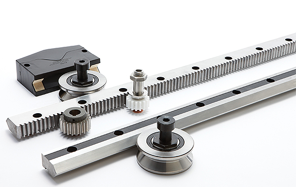
Commercially available RTUs using rack-and-pinion sets are most common. Typical lengths reach 15 meters. Control of the linear unit is integrated as a mathematically coupled axis in the robot controller, which eliminates the need for an additional controller. Many such RTUs maintain accuracy even to strokes of 30 meters by pairing a brushless ac servomotor and planetary gearbox with ground helical rack-and-pinion sets. Other setups use a carriage that moves over a single-edge rail on heavy-duty rollers in a block. Here, the rails are usually rectangular with a rack cut into an inside edge. These can join with curved segments where that’s a helpful layout.

Some RTUs that move the robot about the traveling platform use flat-surface rails made of hardened steel and pair these with cam-follower clusters. Others use an electric motor with a helical bevel reducer and belt to power the platform. Then on the long shuttle axis, the RTU sports an electric gearmotor driving a pinion engaging a rack.
Simulation and programming RTUs
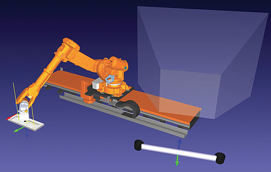
Tools exist to let engineers plan the paths of RTUs and coordinate those with the robot functions. Robot simulation software and even some motion-controller modules let engineers plan tracks, load resulting software onto a controller, and then control the robot and RTU with that one piece of hardware.

Another option is software from dedicated software companies that sell robot development kits, which allow programming of most any brand of robot through APIs. These and myriad other software tools make robot setup easier than ever, especially for teams with moderate motion-control or CNC experience. Initial design iterations usually happen through offline PC programming. Then when personnel install the robot and RTU, the programming software spawns code that loads onto controls. The software drives the RTU and robot through programmed paths to test for problems. Next the installer uses a pendant to position the robot’s gripper, cutter, or end effector to job-specific points in space while the controller records the moves. Otherwise, installers can use a pendant for the entire setup and then polish trajectories on the backend—an increasingly common approach.
Caveat: RTUs complicate robot calibration
After physical setup, RTUs and robots need calibration. The catch is that industrial robots paired with RTUs often make repeatable but not accurate moves, so yield output motion that differs from simulation approximations. Alone, industrial robots average unidirectional repeatability of 0.1 mm to 0.01 mm. Typical axes pair a zero-backlash gearhead and motor, and a controller tracks them all with high-resolution encoders. Boosting output motion accuracy any further gets pricy, as assemblies and components such as gearing introduce lost motion (mostly due to mechanical compliance). Therefore, controls must often compensate for positional error on the scale of millimeters in some cases.

Traditional robot calibration uses costly laser alignment. Sometimes this can decrease output error twentyfold. Otherwise, robot manufacturers offer factory calibration. Dedicated robot-calibration companies also offer services that can account for the effect of an added RTU on overall robot-precision output. Otherwise, dual-camera sensors allow for probing inspection and dynamic measurement via optics and special lighting. Mechanical modes of calibration are another option, though they’re harder to apply to robots on long tracks.
Macron Dynamics
www.macrondynamics.com
Güdel
www.gudel.com/us
ABB Robotics
www.abb.us/robotics
HepcoMotion
www.hepcomotion.com


how do i buy this
I was looking at the pic in the ad that had the round bar support and the opposite side had a gear tooth design with the same round bar configuration. I can’t find this in the literature. Please advise on a USA distributor with contact information.