
Rolling element linear bearings, such as round shafts and bushings, profiled rail guides, crossed roller slides, and even ball screws, have two load capacity specifications — dynamic load capacity and static load capacity — which are based on different operating parameters and performance criteria and are independent of each other. To accurately size and select a rolling element linear bearing or ball screw, it’s essential to understand the differences between them and when each one is used.
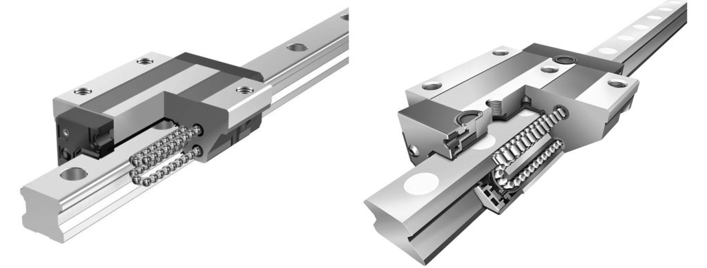
Image credit: Schaeffler Group Inc.
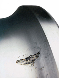
Image credit: The Barden Corporation
Dynamic load capacity, C, is based on empirical testing in which a load that is constant in magnitude and normal to the load-bearing surfaces allows the bearing to achieve a defined travel distance (linear guide) or number of revolutions (ball screw) without fatigue. Fatigue is defined as the presence of flaking on the surface of the rolling elements or the raceways.
The dynamic load capacity is used to determine the rated life of a rolling element bearing. This life is commonly referred to as the L10 life, because it is the life that 90 percent of a group of identical bearings is expected to achieve under set conditions of load and speed.
For linear bearings that use balls:
![]()
For linear bearings that use rollers:
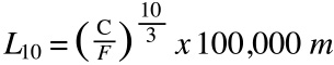
L10 = calculated (rated) life of the bearing
C = basic dynamic load capacity
F = applied load
Dynamic load capacity and the L10 life calculation are defined by the ISO 14728-1 standard for linear bearings, and by the ISO 3408-5 standard for ball screws. The ball screw standard specifies that dynamic load capacity is based on an L10 life of 1 million revolutions. However, the linear bearing standard allows the dynamic load capacity to be specified for an L10 life of either 50,000 m or 100,000 m.
The basis of the L10 life for linear bearings is important to note — especially when comparing linear guides from different manufacturers, or even of different series from the same manufacturer. If a linear guide whose dynamic load capacity is based on 100,000 m is being compared to a linear guide whose dynamic load capacity is based on 50,000 m, one of the following conversions should be applied: Divide the 50,000 m load capacity by 1.26 OR multiply the 100,000 m load capacity by 1.26. (This article explains how the 1.26 conversion factor is derived.)
Keep in mind that the rated L10 life is a theoretical life based on a clean environment, proper lubrication, and correct mounting. The bearing’s actual operating life can be negatively affected by contamination, lack of lubrication, improper mounting, and other factors.
Static load capacity, C0, is the amount of load a bearing can withstand before the sum of the ball and raceway deformation equals 0.01 percent of (0.0001 times) the ball diameter, as defined by ISO 14728-2. Static load capacity is almost always higher than dynamic load capacity because its limitation is plastic deformation of the ball and raceway material, which occurs when the load is applied to the bearing in a static (non-moving) or slow-moving state.
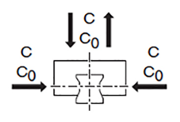
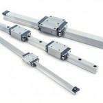
Image credit: Bosch Rexroth Corp.
Static loads are often the result of shocks to the bearing that are unplanned and difficult to quantify. Therefore, linear bearing and ball screw manufacturers recommend applying a static safety factor, depending on the type of application and the operating conditions. The static safety factor is the ratio between the basic static load rating and the maximum combined static load applied to the bearing. It can range from 2 for smooth operating conditions with a low risk of vibrations, to as high as 5 or 6 for applications that may be subjected to severe shock loads.
S0 = static load safety factor
C0 = static load capacity
F0max = maximum combined static load
Feature image credit: Bosch Rexroth Corp.


Leave a Reply
You must be logged in to post a comment.