
Electromagnetism — the relationship between electricity and magnetism — is the underlying principle for the operation of electric motors, as well as generators and transformers. And even though most of us aren’t designing motors (or generators or transformers) from scratch, it’s helpful to have a basic understanding of the concepts and laws that drive their operation.
The foundation of electromagnetism is laid out in Maxwell’s equations — a set of four equations developed by James Clerk Maxwell in the early 1860s. In this article, we’ll look at Faraday’s law of electromagnetic induction, which forms the basis of one of Maxwell’s equations. We’ll also look at Lenz’s law, which keeps Faraday’s law in check.
Faraday’s law of electromagnetic induction
Michael Faraday discovered the relationship between magnetic fields and electricity (electromagnetism) in the 1830s, and although Faraday made many contributions to the study of electricity and magnetism, one of the most important is Faraday’s law of electromagnetic induction, which states:
Any change to the magnetic environment of a coil of wire (a conductor) will cause a voltage (emf) to be induced in the coil. And if the coil (conductor circuit) is closed, current will flow.
The cause of the change in magnetic environment doesn’t matter — it could be caused by changing the magnetic field strength, by moving the magnet towards and away from the coil, by moving the coil into and out of the magnetic field, or by rotating the coil relative to the magnetic field. As long as there is relative motion between the magnetic field and the coil, a voltage will be induced.

Image credit: IGCSE Physics
The mathematic expression for Faraday’s law of electromagnetic induction shows that the induced voltage is equal to the number of turns in the coil multiplied by the time-based change of the magnetic flux.
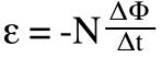
ε = induced emf (V)
N = number of turns of coil
Φ = magnetic flux (Wb, V·s)
t = time (s)
Note that magnetic flux (Φ) is the product of the magnetic field (B) and the area of the coil (A): φ = BA
Lenz’s law
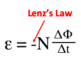
The negative sign (“-“) on the right side of the equation above comes from Lenz’s law and indicates that the induced emf occurs in a direction opposite to the magnetic flux.
Lenz’s law ensures that Faraday’s law adheres to the principle that energy must be conserved, stating that:
When emf (voltage) is generated by a change in magnetic flux, the polarity of the induced emf generates a current whose magnetic field is in a direction that opposes the change that produced it (the original magnetic field).
In other words, the induced magnetic field always works to keep the magnetic flux constant. If the magnetic flux decreased, the magnetic field created by the induced current would add to it. And if the magnetic flux increased, the magnetic field created by the induced current would subtract from it. In both cases, the total magnetic flux remains constant.

Image credit: C. R. Nave, Georgia State University
Likewise, the induced emf will oppose the change that created it. In other words, the induced emf (voltage) will be in a direction opposite to the voltage that created it. In a motor, this means the induced emf (commonly referred to as back emf) opposes the supply voltage.

Supply = 195 V
Back emf = -45 V
Net voltage in circuit (V = IR) = 10 * 15 = 150 V
195 V + -45 V = 150 V
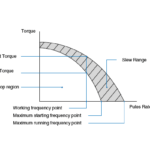
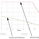
Back emf is directly related to motor speed: when motor speed increases, so does back emf, and vice-versa. This is why, for example, a DC motor’s torque and speed characteristics have an inverse, linear relationship.
As the load (torque) on the motor is increased, the motor slows down. The slower the motor spins, the lower the back emf (opposing the supply voltage) and the less voltage the motor uses just to overcome this back emf. Therefore, the voltage and current across the motor increase. This additional current allows the motor to produce the extra torque it needs to regain its speed with the increased load.
Circuit diagram and example taken from New South Wales, Department of Education and Training, 2007.

Leave a Reply
You must be logged in to post a comment.