No motor subtype satisfies all applications, as all have their own benefits and drawbacks. Even so, axes that need incremental strokes often use dc motors that are either stepper or servomotors. Very advanced designs incorporate linear motors to do away with gearboxes, belts and pulleys, ballscrews, leadscrews, and other power-transmission components — for high accuracy and positioning resolution. Even so, rotary-motor-based designs (including those running off stepper motors) are still first choice for most linear axes. That’s because they’re cheaper than linear-motor setups and they usually offer suitable performance.
Read more about rotary and linear steppers in FAQ: How do linear stepper motors compare to familiar rotary types?
Stepper motors tend to be bulky if the design needs higher power but are cost effective and run off simple drive architecture — so are a leading choice for smaller machines.
There is complexity in stepper-motor sizing, but basic understanding of how they produce torque simplifies the process. Here are some key things to remember:
• All motion-design inertial mismatches dramatically alter torque-speed curves, which is why safety margins to 30 to 50% are common when sizing stepper-based linear axes.
• Manufacturers of rotary stepper motors publish pull-in curves that plotting start-stop regions for the motors. These chart the top frequencies at which a loaded stepper can instantly stop and go without losing steps.
• No motors can instantaneously stop and start — so stepmotors must decelerate and accelerate into and out of movements at rates plotted on pullout curves at what are called slew rates. Pullout curves plot top frequencies at which stepmotors can run before desynchronizing.
First narrow down the stepmotors being considered by first defining the motion profile — including the time the application allows for positioning and acceleration. Here, the application may also necessitate specific positioning increments at set levels of accuracy and resolution.
Then calculate application speed, load inertia, and load torque requirements without forgetting the torque needed for periods of acceleration.
Case in point: Let’s say we’re going automate a machine axis with a stepmotor fitted with a leadscrew. Assume the actuator must deliver 10 lb of force and travel three inches (or 0.0762 meters) within eight seconds. Also assume that the actuator must function for 1,000,000 life cycles. Linear velocity is 0.375 in./sec or 9.525 mm/sec.
First we consult manufacturer life-expectancy charts:
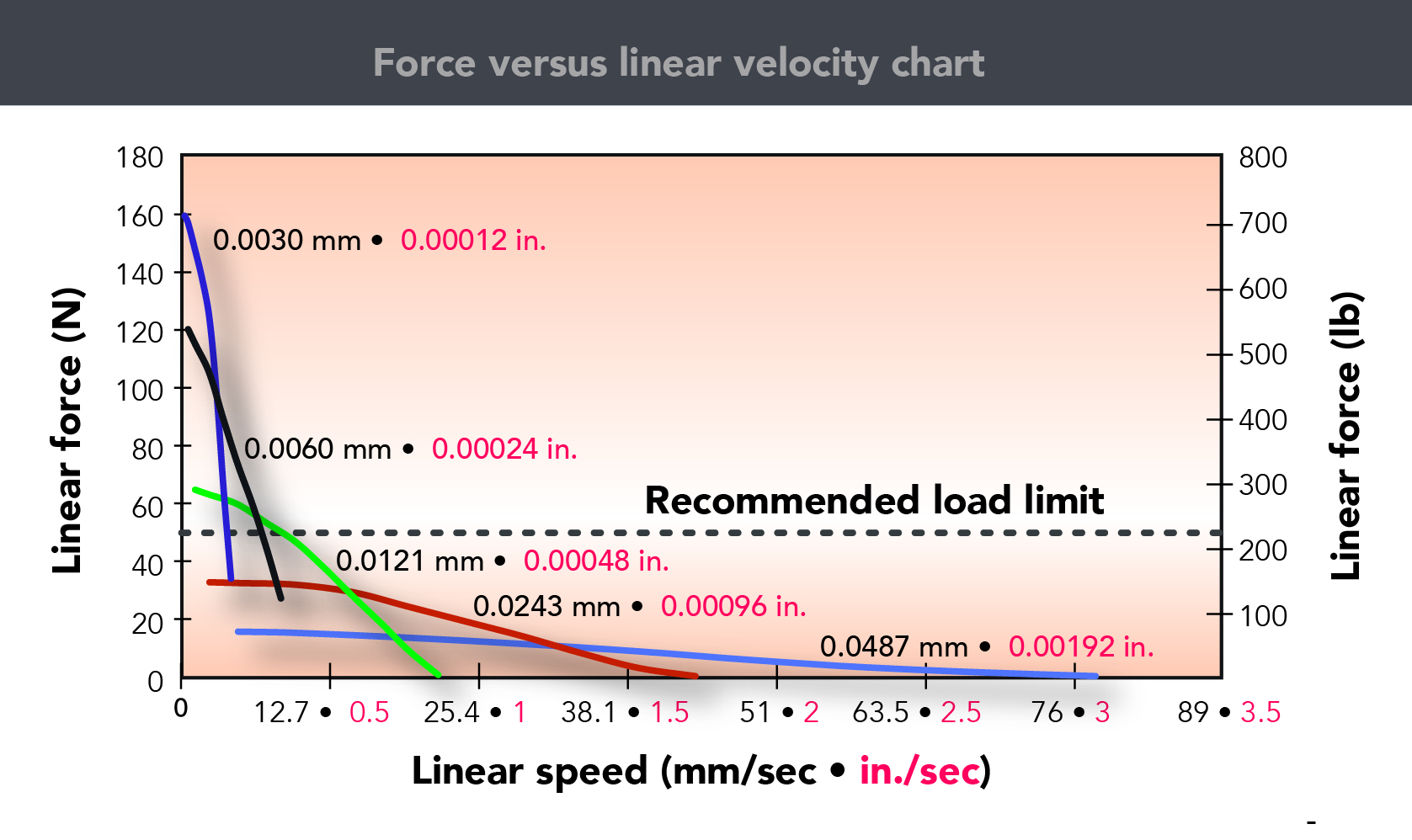
(Note that this example actuator life-expectancy chart is courtesy HaydonKerk of AMETEK.)
The length of life needed for this application lets us load the actuator to 50% of rated maximum capacity.
So next, we determine acceptable actuators by their load rating factored by this value.
10 pounds divided by 0.5 indicates that we need an actuator with a 20-lb load rating. Converted to Newtons, this is 88.96 N.
This means that required power is:
Next refer to the manufacturer motor documentation to select an appropriate motor:
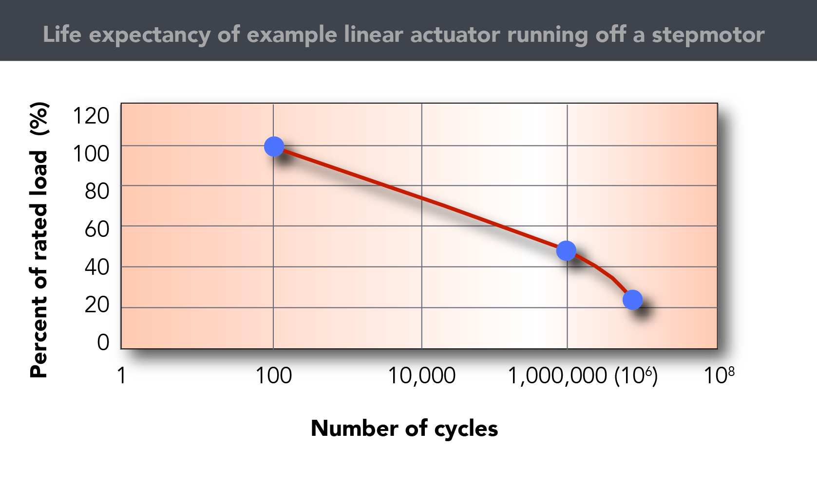
Finally, determine the resolution and thread type using a force versus linear velocity chart for the 43000 series:
In conclusion, a threaded rod of 0.00096 in. (or 0.0243 mm) is suitable for the application at hand.
Warning: Always check with the actuator manufacturer before making a final selection and request all relevant documentation upfront.
More information on how to size and use stepper motors that integrate rotary-to-linear motion:
PDF Download: Ametek HaydonKerk’s Stepper Motor Linear Actuators 101
Motion Control Tips: What are Lead Screws? Technical Summary for Motion Engineers
Thank you to Marcia Colucci at Haydon Kerk of AMETEK for information on this topic.




Leave a Reply
You must be logged in to post a comment.