Like most linear motors, a linear stepper motor is essentially a variation of the rotary design, cut radially and laid out flat. Similar to their rotary counterparts in operation and performance, linear stepper motors are typically run as open-loop systems and are capable of providing high resolution at high speeds and accelerations.
The linear stepper motor almost exclusively employs a hybrid design, with two main parts—a base (also referred to as a platen) and a slider (also referred to as a forcer). Unlike other linear motor designs, in a linear stepper motor, the platen is a passive component—a steel (or stainless steel) plate with slots milled into it. The forcer contains laminations with slotted teeth, motor windings, and a permanent magnet. The teeth of the forcer concentrate the magnetic flux that is created when current is applied to the coils. The forcer teeth are also staggered in relation to the platen teeth—typically by ¼ tooth pitch—to ensure that constant attraction is maintained and that the next set of teeth will come into alignment as current is switched in the coils. For each full step of the motor, the forcer moves ¼ tooth pitch.
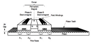
Image credit: Parker Compumotor
The magnetic flux between the forcer and the platen creates a very strong magnetic attraction, so bearings—either mechanical roller bearings or air bearings—are typically integrated into the linear motor system to maintain the correct air gap between the forcer and the platen. When air bearings are used, the platen serves as the air bearing surface.
Both full step operation and microstepping are possible with linear stepper motors, but microstepping is often used in order to minimize resonance, which occurs when the rate of input pulses coincides with the natural oscillation frequency of the motor. Resonance causes a loss of torque and can lead to missed steps and errors in positioning. Microstepping also increases the motor’s resolution, although at the expense of torque.
Microstepping is a common control method for both rotary and linear stepper motors, in which the motor controller subdivides the motor’s step angle and drives each phase with current in an ideal sine wave. The step angle can be divided by up to 256 times, resulting in much smaller steps for greater control of the motor’s rotation. Additionally, the sine wave currents are 90 degrees apart, so as current in one winding increases, it decreases in the other winding. This results in smooth running and more consistent torque production than full- or half-step operation.
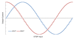
Image credit: Texas Instruments Inc.
The primary drawback to linear stepper motors is that they have poor speed-force relationships. This means that while they can produce high force at low speed, their force production drops sharply as speed increases. But for applications that are suitable for open loop operation with low to moderate force requirements, linear stepper motors offer a solution that is simple to set up and operate and that provides high resolution at high speeds.



Leave a Reply
You must be logged in to post a comment.