
Image credit: Kaydon Bearing
In any motion system, understanding the type and direction of applied and resultant loads is important for determining bearing life and analyzing deflection. In linear motion systems, we typically use Cartesian coordinates (X, Y, and Z) to define the placement and direction of loads. But for rotating components such as screws, rack and pinion drives, or belt and pulley systems, loads are typically described as axial or radial — terms adopted from rotary bearing technology. These terms are also sometimes used to describe loads on linear guides, although their relation to the direction of loading can vary, depending on the manufacturer and the type of guide.
Here, we’ll look at how radial and axial loads affect linear motion systems and explain the terms commonly used to describe loads on linear guides.
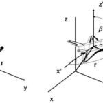
In this discussion, we use the convention shown below for defining the X, Y, and Z axes. The X axis is along the direction of travel, the Y axis is horizontal and perpendicular to the direction of travel, and the Z axis is vertical.
(Note that in some cases, manufacturers designate the Y axis along the direction of travel and the X axis as horizontal and perpendicular to the direction of travel.)
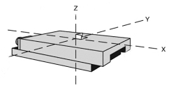
Image credit: Newport
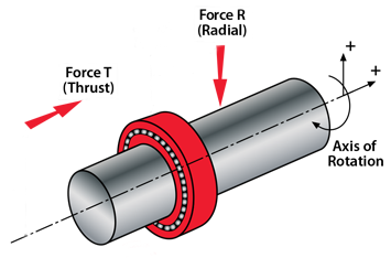
Axial loads: Parallel to direction of travel
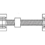
Rotary bearing terminology defines axial loads as those occurring parallel to the axis of rotation (the X axis), and rotating linear drives — such as screws, belt and pulley systems, or rack and pinion drives — also use this terminology. Axial loads are the loads the system must overcome to produce motion, and are also commonly referred to as thrust loads. In ball and lead screw drives, axial loads can also lead to deflection or buckling of the screw shaft.
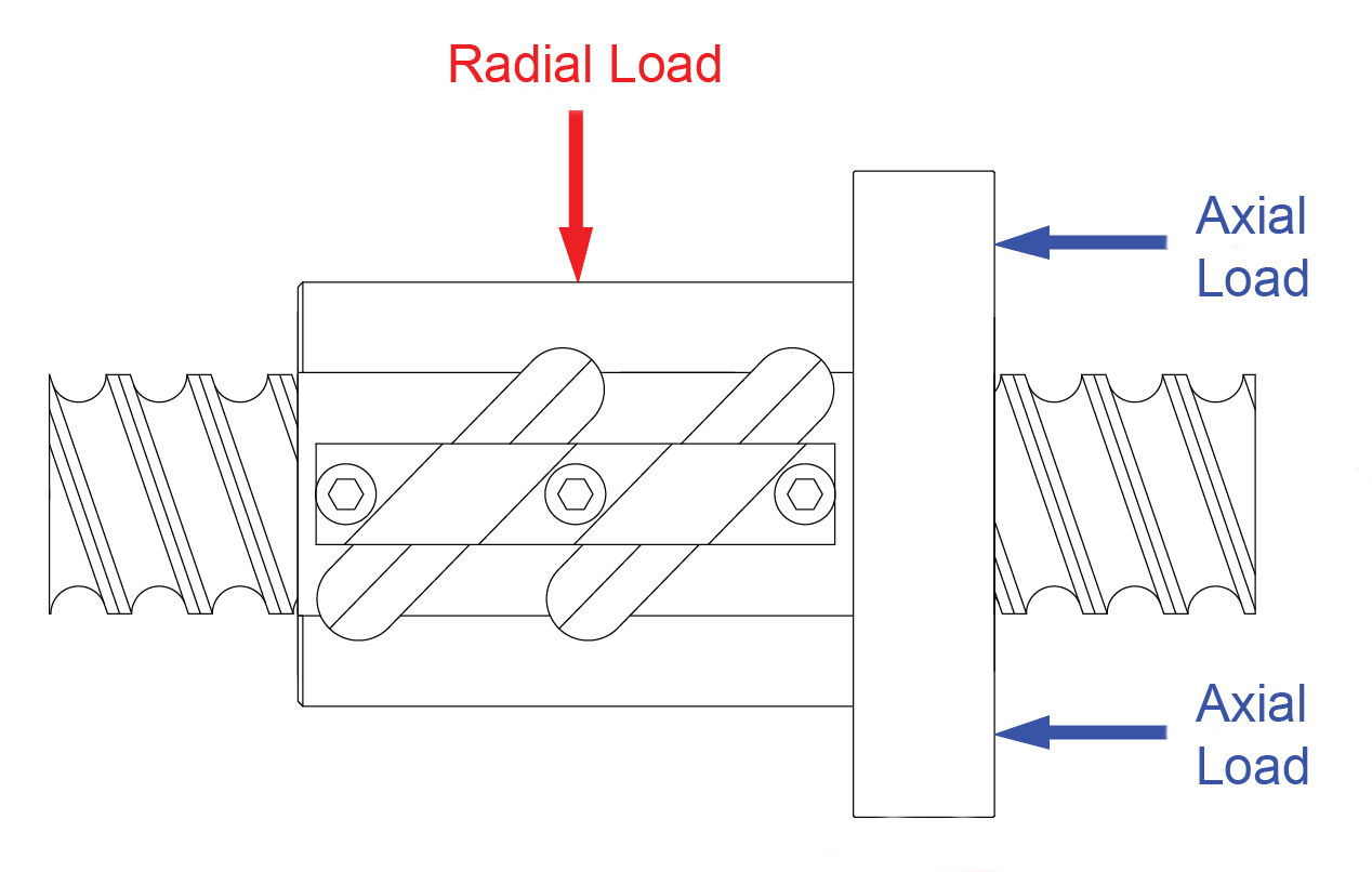
Image credit: Rockford Ball Screws
Notice that linear guides don’t support axial loads because their single degree of freedom (degree of motion) is along the X axis.
Radial loads: Perpendicular to direction of travel
Like rotary bearings, linear drive terminology defines radial loads as those occurring perpendicular to the axis of motion, in the Y or Z direction. (Note that loads occurring at an angle between the three orthogonal axes can be resolved into components that occur purely in X, Y, or Z.)
Because linear drive mechanisms are only designed to withstand axial loads — not radial loads — they’re typically used in conjunction with linear guides, which support any radial loads in the Y (horizontal) or Z (vertical) directions.
For linear guides, terminology varies when it comes to describing loads acting perpendicular to the axis of motion, depending on the type of guide and whether the load is acting in the Y or the Z direction. For example, because round shaft linear guides have the ability to rotate, the term “radial load” is typically used.
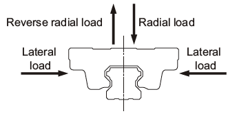
Image credit: THK
For non-rotating linear guides — such as profiled rail guides, crossed roller guides, or dovetail slides — radial loads that occur along the Z axis are often described as “normal loads,” “tension loads” (for those in the positive Z direction) or “compression loads” (for those in the negative Z direction)
Loads that occur along the Y axis (horizontal, perpendicular to the direction of motion) are often termed “side loads,” “lateral loads,” or “transverse loads.” It’s important to note that although linear guides are designed to handle loads in both the Y and Z directions, the type of bearing and arrangement of the raceways may lead to different load capacities in different directions.
The naming convention for loads on telescoping guides, which are often mounted on their sides, differs from that of other linear guides. With telescoping guides, radial loads, which occur in the vertical direction, act toward the side of the guide. And axial loads, which occur in the horizontal direction, perpendicular to the direction of travel, act toward (or away from) the top of the guide.
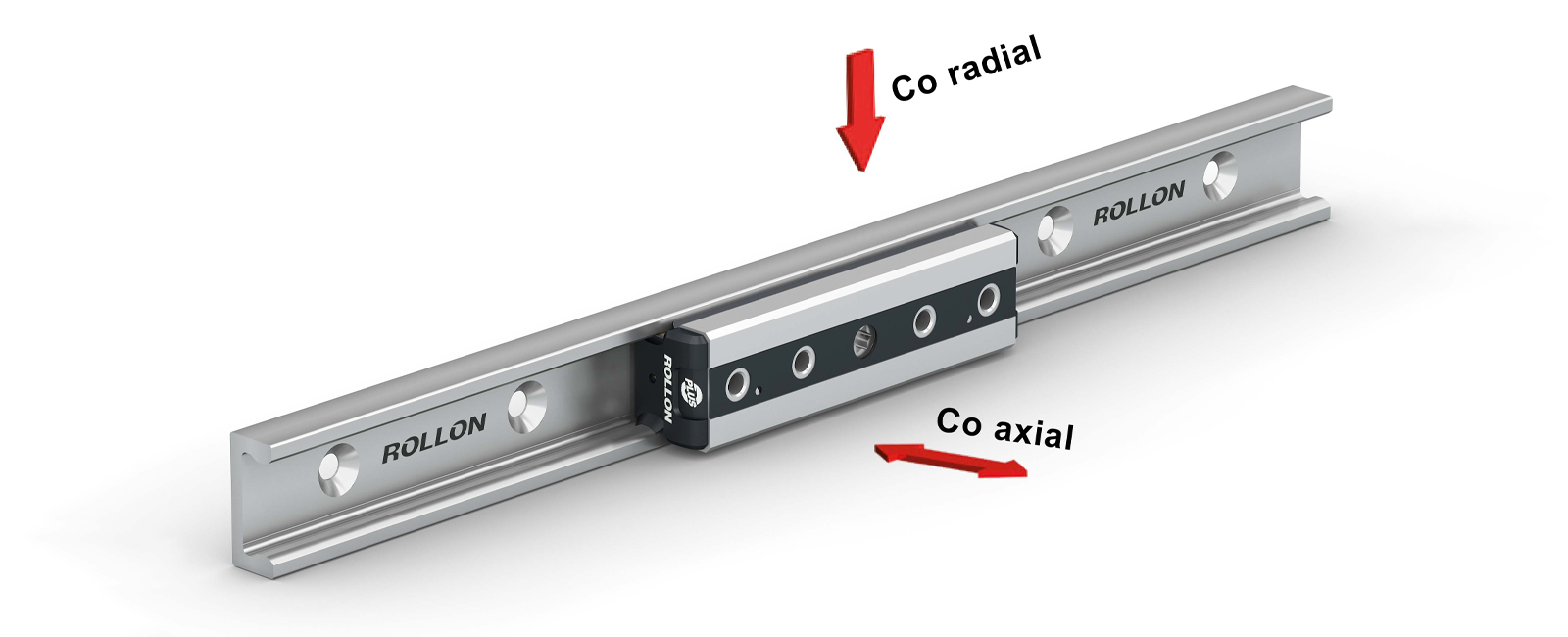
Image credit: Rollon


Leave a Reply
You must be logged in to post a comment.