
Encoder technology generally falls into three categories: optical, magnetic, and capacitive, with optical and magnetic encoders making up the bulk of the industrial automation encoder market. Not very long ago, the choice between optical and magnetic technologies was primarily a matter of resolution. If encoder resolution below 5 microns was required, optical was the only choice. But improvements in manufacturing and signal processing now allow magnetic linear encoders to operate at resolutions down to 1 micron.

Where optical linear encoders use a scale with periodic graduations, a light source, and a photo-detector to determine position, magnetic linear encoders use a read head with a sensing element in conjunction with a scale that is magnetically coded with alternating polarity. The alternating north and south magnetic poles are spaced at a precise distance, referred to as the pole pitch. The read head contains either Hall or magnetoresistive sensors, and as the read head moves over the tape, it detects the magnetic poles on the scale through either a change in voltage or a change in magnetic resistance.
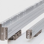
The scale used in magnetic linear encoders is multi-layered, including a flexible base layer with an adhesive backing, the magnetic scale, and in many cases, a plastic or stainless steel cover strip to protect the magnetic scale. Because it is flexible and has an adhesive backing, the scale assembly is sometimes referred to as a “magnetic tape.”

One advantage of magnetic linear encoders over optical versions is that the magnetic tape can be provided in very long lengths — real-world application examples include magnetic scales upwards of 50 meters long. But for incremental encoding, this means the homing sequence to a single reference mark could require traversing the entire length of the encoder. This is why magnetic linear encoders often include distance-coded reference marks. These marks are magnetic poles that are included on the scale in addition to the standard magnetic poles. The reference marks are spaced individually (i.e. their spacing is not the same along the length of the tape) and indepently of the standard magnetic poles. After traversing two reference marks, the encoder can determine absolute position based on the position of the first reference mark, the distance between the two marks, the direction of travel, the length of each magnetic pole, and the basic increment (distance between odd reference marks).
Image credit: Heidenhain
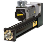
In order to provide absolute position measurement, magnetic encoders typically employ two magnetic tracks on the same scale — an incremental track and an absolute track. The absolute track is coded with a specific pattern that gives each position a unique “word” that is read by the sensor. The read head contains two sensors — one for each track. The common setup uses a Hall sensor to read the absolute track and a magnetostrictive sensor to read the incremental track. On startup, the encoder reads the absolute track to determine its position, and then during movement, it reads the incremental track for position tracking and measurement.
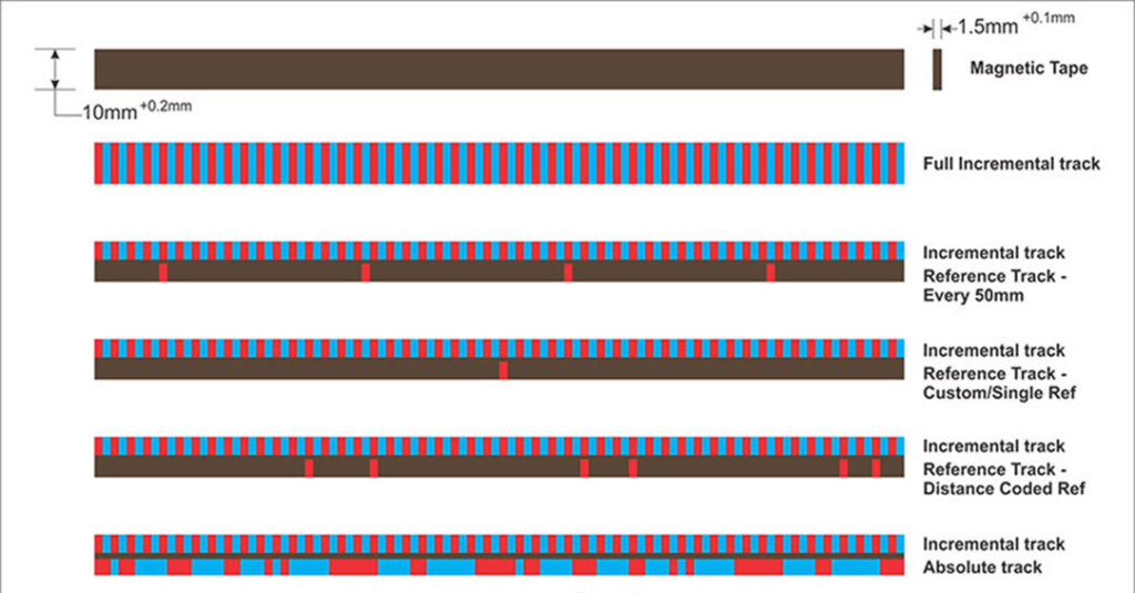
Image credit: Electronica Mechatronic Systems
Magnetic encoder technology virtually eliminates one of the primary drawbacks of optical encoders — sensitivity to dirt, dust, liquids, and other debris. Because optical designs rely on either the reflection or refraction of light, anything that interferes with the light’s transmission can cause a problem with the signal. Because magnetic coders don’t rely on “line of sight” to measure position, contamination doesn’t affect their performance. (The exception is any contamination or environment that is magnetic, which will interfere with a magnetic encoder’s ability to measure position.) In addition, optical encoders require that a very small, precise air gap — typically in the range of 0.25 mm — be maintained between the scale and the detector, and this gap can be compromised with vibrations or shocks. Magnetic encoders can operate with gaps up to several millimeters and are more tolerant of variations in the gap distance.
Feature image credit: Renishaw plc

Leave a Reply
You must be logged in to post a comment.