
Linear bushings, also known as ball bushings, are linear bearings that ride on a hardened, round shaft to provide linear guidance with low friction. The first linear bushing designs were patented in 1945 and became commercially available in the 1950’s. Until the introduction of profiled rail linear guides in the 1970’s, linear bushings served as the primary form of linear motion for application that didn’t require the extreme load capacity and accuracy of machined ways. As linear bushing designs evolved, features such as increased load capacities and self-alignment capabilities have helped maintain their place as one of the leading choices for linear guides in motion applications.
Linear bushings consist of load-bearing plates, a ball retainer, steel balls, end caps or rings, and seals. External loads are transferred from the load plates (analogous to the outer race of a radial bearing), through the steel balls, and to the shaft (analogous to the inner race of a radial bearing). Traditional linear bushing designs produced point contact between the balls and the load plates. This point contact provided extremely low friction, but also limited the load capacity of the bushing. Although linear bushings are still available with this design, most current designs incorporate a groove in the load plate to provide better conformity with the load-carrying balls. The change from point contact to conformity increases the load capacity by three times that of a traditional design, which results in 27 times the dynamic bearing life.
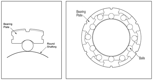
Image credit: Thomson Industries, Inc.
Despite the higher load capacities and stiffness of profiled rail guides, one of the benefits that linear bushings provide is their suitability for applications where high-precision machining of mounting surfaces and alignment of components is not feasible. For example, in order to support moment loads, linear guides (whether shafts or profiled rails) are often used in pairs. If the guides aren’t perfectly aligned with respect to their height, profiled rail versions will bind, experience high friction, and have a greatly reduced life. Linear bushings, on the other hand, can rotate (roll) around the shaft, compensating for the shaft misalignment. As a rule of thumb, 1 to 2 mm of height difference can be compensated when shafts are mounted 300 mm or more apart.
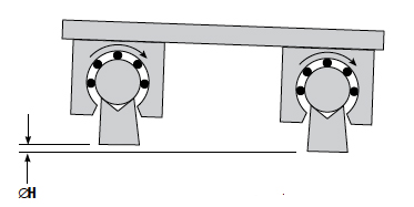
Image credit: Thomson Industries, Inc.
In addition to their inherent roll capability, linear bushings can also be “self-aligning,” meaning they can rotate in the pitch and yaw directions, allowing them to compensate for flatness or alignment errors or deflection in the shaft. This self-alignment capability is made possible by the design of the load bearing plates, which can be sharply crowned, gradually crowned, or radiused.
Sharply crowned designs use bearing plates that are thinner on the ends than in the middle, allowing the plate to “rock” around a pivot point at its center. This gives the bushing a misalignment tolerance of ±0.5 degree. Sharply crowned designs can carry higher loads, but also increase contact stress between the bearing plates and the bore. This can result in the bearing plate becoming embedded in the bore, which increases the clearance between the shaft and the bushing.
Gradually crowned load plates operate on the same principle as sharply crowned designs, but allow more contact area between the load plate and the bore, which reduces contact stress. This reduces the likelihood of the bearing plates becoming embedded in the bore, so the proper clearance is maintained between the shaft and the bushing. For this reason, gradually crowned versions are more common than sharply crowned designs
The third bearing plate design, sometimes referred to as “radiused,” incorporates an outer ring along the center of the bushing housing. The ring provides a hardened surface for the bearing plates (which are flat, rather than crowned) to contact. This design allows the load plates to self-align in all three directions: roll, pitch, and yaw. The downside of this design is that it requires more, smaller balls in order to operate properly, which makes it more susceptible to contamination.
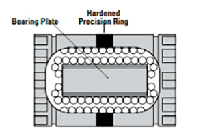
Image credit: Thomson Industries, Inc.
Sealing is always an important consideration in recirculating linear bearings, but it becomes even more critical with self-aligning linear bushings. When a bushing tilts, a standard seal will lose contact with the shaft and become ineffective. To prevent this, self-aligning bushings are generally offered with floating seals, which maintain consistent contact with the shaft to ensure protection against contaminants. Floating seal designs also minimize seal friction.
In addition to making up for inaccuracies in mounting surfaces, alignment, or shaft deflection, self-aligning linear bushings also ensure even distribution of the load over the full length of the bushing. This prevents edge pressure between the end of the bushing and the shaft, for low friction and smooth running characteristics.
Feature image credit: Alexander Slocum, “MIT Bearing Fundamentals Topic 10”

Leave a Reply
You must be logged in to post a comment.