
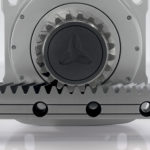
A rack and roller pinion system is a variation on the traditional rack and pinion that replaces the toothed pinion (gear) with a cage-type pinion that incorporates bearing-supported rollers.
Each roller in the pinion is supported by two needle bearings, which eliminates the sliding friction that occurs in traditional rack and pinion systems. This greatly reduces heat and wear in the pinion, resulting in efficiency of up to 99 percent.
The tooth profile of the rack is unique as well. It is created by placing points in even spacing around a circle, and, as the circle rolls on a flat surface, following those points until they reach the surface. The paths created by these points are cycloidal curves that form a tooth-like profile. Next, rollers, which serve as pinion teeth, are placed at each point on the circle. As the circle once again rolls along a flat surface, the rollers modify the curves to create the actual gear teeth. The result is a tooth profile that allows the pinion rollers to approach the teeth at a tangent, so they roll down the tooth face smoothly. Not only does this significantly reduce noise, this tooth design can be modified to allow two or more rollers to be loaded in opposition (preloaded), which virtually eliminates backlash.

Image credit: Nexen Group, Inc.
When properly installed and operated, some rack and roller pinion models can achieve positioning accuracy of ±30 μm, and positioning accuracy does not degrade until the needle bearings reach the ends of their lives. The needle bearings are lubricated for life and sealed, so they don’t require lubrication.
For corrosion resistance, racks and pinion bodies can be made from stainless steel, steel with a hard chrome coating, or nickel-plated steel. And some models can be operated without lubrication of the rack or pinion, as long as speeds don’t exceed 0.5 m/s. Racks can also be made of thermoplastic, which is self-lubricating and resists corrosion from many types of contaminants and chemicals.
Mounting and operating considerations
In order to operate properly and provide optimal system life, rack and roller pinion systems require constant preload over their entire length. This means the rack and the linear guide system (profiled rail, for example) must be mounted parallel to one another. If the rack and the guide converge (move toward each other) at any point, the preload on the pinion will be excessive, which can cause noise and binding, resulting in lower pinion bearing life. If the rack and the guide diverge (move away from each other) at any point, the pinion preload will be reduced or lost, resulting in system backlash, noise, and reduced system life.
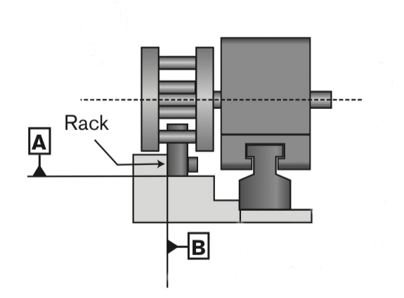
Image credit: Nexen Group, Inc.
Applications and uses
Rack and roller pinions can often achieve better positioning accuracy and repeatability than traditional rack and pinion systems (without additional components such as split-pinions or dual-pinions). They can be provided in much longer lengths than ball screw drives, with speed capability of up to 11 m/s, regardless of length.
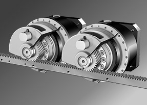
Image credit: ATLANTA Drive Systems, Inc.
Linear motors offer the long length and high speed capabilities of rack and roller pinion systems, but iron core motors are often required for dynamic applications with high loads, which means that cogging forces must be mitigated and cooling may be required. Belt drives can also provide long stroke lengths and high speeds, but with much lower rigidity and lower load capacities.
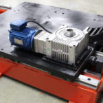
Compared to these alternatives, the “sweet spot” for a rack and roller pinion system could be described as an application that requires long stroke length, high travel speed, and good thrust force capability, all while maintaining good positioning accuracy and repeatability. Examples are robot transfer units, gantry robots, and large machining or cutting equipment, such as waterjet cutters. And an application with any combination of these requirements, that takes place in a cleanroom environment or requires very high corrosion resistance, would also be well-suited for a rack and roller pinion system.


Great Information! Thanks for sharing.