
Stepper motors move in discrete steps when current is applied to coils in the stator. The size of the step is determined, in part, by the number of phases in the stator. In general, the more stator phases, the smaller the basic step angle and the higher the motor’s resolution.
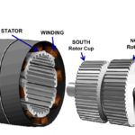
Stepper motors come in three basic types of construction: permanent magnet, variable reluctance, and hybrid. Permanent magnet stepper motors have a permanent magnet rotor, whereas variable reluctance types have a toothed rotor made of soft iron. Hybrid stepper motors combine the features of the permanent magnet and variable reluctance types, using a permanent magnet rotor with iron teeth.
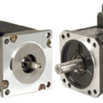
The hybrid stepper motor is most commonly used in industrial applications, due in part to its small basic step angle, higher torque production, and better holding and detent torque than permanent magnet or variable reluctance designs. This discussion focuses on the hybrid stepper motor design.
The stator of a hybrid stepper motor consists of poles with teeth, and each pole has a winding. Phases are made up of poles connected by their windings. When current is applied to a phase, each pole in that phase will be energized and magnetized. Poles 180 degrees opposite each other are magnetized with the same polarity.
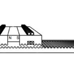
The rotor of a hybrid stepper is made up of two parts, often referred to as “cups.” Each cup has 50 teeth, and the teeth on one cup are magnetized as north poles, while the teeth on the other cup are magnetized as south poles, for a total of 100 poles (50 pole pairs). When the stator is energized with current, the rotor moves so that its teeth line up with the magnetized teeth of the stator. The amount the rotor moves with each pulse of current is defined as the step angle.
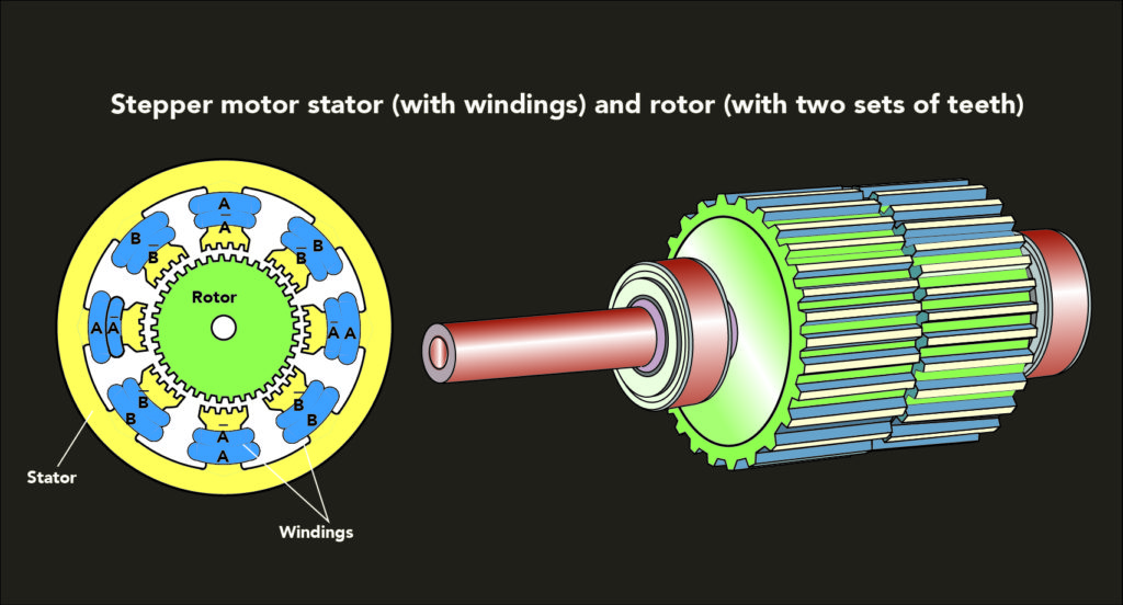
A pole is an area in a magnetized body where magnetic flux is concentrated. A pole pair is a combination of one north pole and one south pole.
Hybrid stepper motors are often classified by the number of phases in the stator, with the majority of hybrid steppers having either 2 phases or 5 phases.
A 2-phase stepper motor typically has eight poles, or four poles (two pole pairs) per phase. When the stator phases are energized, the rotor moves one-quarter of a tooth pitch to align with the energized stator poles. Since the rotor has 50 teeth and moves ¼ tooth pitch at a time, the motor makes 200 steps per revolution, giving a basic step angle of 1.8 degrees.
Step angle = 360 ÷ (2 * # stator phases * # rotor pole pairs)
Step angle = 360 ÷ (2 * 2 * 50) = 1.8 degrees
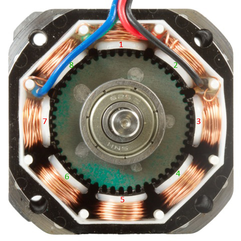
Image credit: Phidgets
A 5-phase stepper motor has ten poles, or two poles (one pole pair) per phase. In this configuration, the rotor only needs to move one-tenth of a tooth pitch to line up with the energized stator poles. With 50 rotor teeth moving 1/10 tooth pitch with each step, the 5-phase motor makes 500 steps per revolution, resulting in a basic step angle of 0.72 degrees.
Step angle = 360 ÷ (2 * 5 * 50) = 0.72 degrees

Image credit: Oriental Motor USA Corp.
The smaller step angle of a 5-phase stepper motor provides higher resolution than the 2-phase design, and microstepping control can produce even greater resolution. (Note that the accuracy of movement is determined by the motor’s mechanical accuracy, which depends on the quality of the components used in the motor construction and on the methods used for manufacturing and assembly.)
Although higher resolution is an inherent benefit of stepper motors with more stator phases, the primary reason for using a higher-phase motor (5-phase versus 2-phase, for example) is that more phases, and therefore smaller steps, produce less torque ripple and more usable torque. Another benefit of more stator phases and a smaller step angle is that the motor is less likely to miss steps due to undershooting or overshooting, making it more reliable in open loop operation.

This posting does convey the operation correctly, and in an easy to understand manner. Thanks. A bit of information about the driving power would have been even more educational, als an explanation of full step and half step modes.