
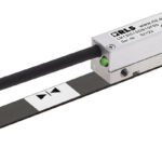
Both LVDTs (linear variable differential transformers) and resolvers are measuring devices that convert displacement into an electrical signal. As its name implies, an LVDT is used for linear measurement, while a resolver is used to measure rotary, or angular, displacement.
In terms of construction and operation, the most significant similarity between an LVDT and a resolver is that they are both transformer-based measuring devices, meaning they use electromagnetic induction to transfer, or induce, voltage from a primary winding to secondary windings.

Image credit: Honeywell International
An LVDT has three windings — a primary winding and two secondary windings — wound around a hollow form. The primary winding is located between the two secondary windings, and the secondary windings are wound in series but in opposite directions. These three windings make up the transformer. Housed inside the bore of the transformer is a ferromagnetic core, which can move freely along the internal bore. This core is attached to the part being measured via a non-magnetic shaft, or push rod.
When a voltage is applied to the primary winding, magnetic flux is produced and couples to the secondary windings via the ferromagnetic core. This magnetic flux induces a voltage in each of the secondary windings.
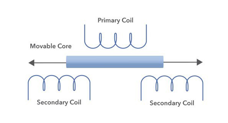
Image credit: United Electronic Industries
The location of the core with respect to each of the secondary windings determines the amount of voltage induced in each, and the differential voltage output between the two secondary windings determines the distance moved. The direction of movement is determined by the whether the output voltage is in phase or out of phase with the primary voltage.
A resolver is also a transformer-based device, using three windings — a reference winding on the rotor (which is attached to the component whose position is being measured, such as a motor shaft) and two secondary windings on the stator. The stator windings are mechanically oriented at 90 degrees to each other (in quadrature) and are referred to as the sine and cosine windings.

Image credit: Advanced Micro Controls, Inc.
For brushless resolvers, voltage is supplied to the reference winding on the rotor by a rotary transformer, which induces voltages in the secondary windings on the stator. The induced stator voltages are equal to the reference voltage multiplied by the sine and cosine (respectively) of the input shaft angle from a defined zero point.
The precise shaft position is determined by taking the ratio of the voltages in the secondary windings, and the direction of rotation is determined by which signal (sine or cosine) is leading.
Another transformer-based device to measure rotary displacement is the rotary variable differential transformer (RVDT). An RVDT operates much like an LVDT, with a ferromagnetic core, one primary winding, and two secondary windings. The secondary windings are wound 180 degrees out of phase. But in the case of an RVDT, the shaft acts as the core and the windings are located on the stationary part of the assembly.
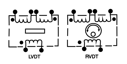
Image credit: Data Device Company
When voltage is applied to the primary winding, the core induces voltages in each of the secondary windings. These voltages vary linearly with the angular position of the shaft (core), and the differential voltage output determines the angular position of the shaft. Similar to an LVDT, the direction of movement (rotation, in this case) is determined by the phase difference between the output voltage and the reference (input) voltage.
A disadvantage of rotary variable differential transformers is that their measuring capability is linear over a limited range — typically ±40 degrees of rotation, although some designs can be used for up to ±70 degrees of rotation.


Leave a Reply
You must be logged in to post a comment.