
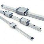
In the context of profiled rail guides with recirculating balls, the raceway geometry defines how the load-carrying balls are positioned relative to the raceways of the rail and the bearing (aka “carriage” or “slide”). The two most common raceway geometries are referred to as circular arc and Gothic arch, but some manufacturers have adopted a third raceway design, referred to as offset Gothic arch. While neither design can be deemed “better” than the others, the raceway geometry affects performance factors such as stiffness, friction, and moment load capacity.
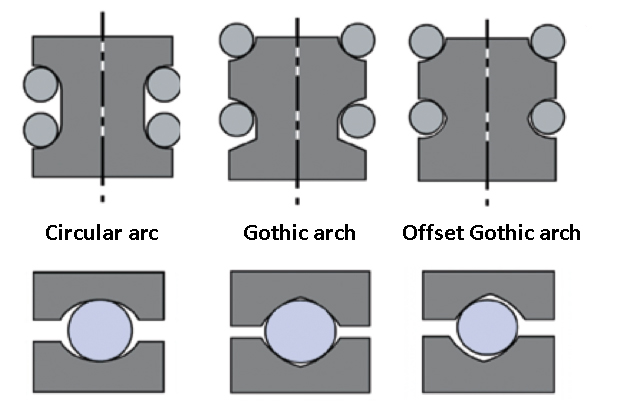
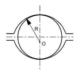
Image credit: NSK
Circular arc raceway geometry
The defining feature of circular arc raceway geometry is that it allows the load-carrying balls to make contact with the raceways at two points. This results in less differential slip, and therefore, lower friction, than the other geometries. An important design parameter of profiled rail guides with circular arc contact is that the raceway curvature is in the range of 51 to 52 percent of the ball diameter. This relatively low curvature means bearings with circular arc geometer generally have higher load capacities than other designs. (For an in-depth look at the relationship between raceway curvature and load capacity, check out this article.)
The two-point contact of circular arc designs also allows some self-adjusting capability, so the requirements for precision and rigidity of the mounting base are less stringent than the requirements for other geometries. It’s important to note that because the circular arc geometry has only two-point contact, two rows of balls on each side of the carriage (bearing) are required in order to support lift-off loads.
Raceway arrangement: Back-to-back or face-to-face
There are two sub-types of profiled rail guides with circular arc geometry, specified by how the contact lines between the load carrying balls and the raceways are oriented: in a “back-to-back” (aka “O”) arrangement or a “face-to-face” (aka “X”) arrangement. The geometry and length of these contact lines determine how well the bearing can support overturning, or moment, loads.
The back-to-back arrangement provides a larger moment arm between the raceways, so it has a better roll moment capacity and is better suited for use in a single-rail arrangement with moment loads present. On the other hand, the lower moment rigidity of the face-to-face arrangement allows it to withstand some amount of distortion, or inaccuracy, in the mounting surface. The face-to-face arrangement also provides equal load capacities in all directions (downward, lift-off, and side loads).
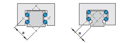
The face-to-face design (right) is also known as the “X” arrangement because the contact lines between the balls and the raceways point inward, forming an “X” inside the rail.
Image credit: Bosch Rexroth
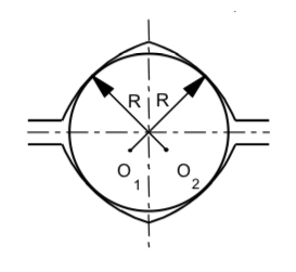
Image credit: NSK
Gothic arch raceway geometry
The Gothic arch raceway geometry provides four-point contact for each load-carrying ball, which provides higher rigidity. However, bearings with a Gothic arch geometry — despite having four-point contact — generally have lower load capacities than similar circular arc designs. This is because the raceway curvature is higher, at 55 to 60 percent of the ball diameter. (Recall from above that a higher raceway curvature means lower load capacity.) The four-point contact also reduces the bearing’s ability to compensate for inaccuracies in the mounting base, so mounting requirements for bearings with Gothic arch geometry are generally more stringent than for those with circular arc geometry.
The main benefits of Gothic arch designs are their ability to withstand loads from any direction and their relatively high moment load capacities. Accordingly, bearings that use only two rows of recirculating balls (one row on each side of the bearing), will typically have a Gothic arch arrangement.
Differential slip
The most significant limitation of the Gothic arch design is a phenomenon known as differential slip. In a recirculating ball bearing, the contact area between the ball and the raceway is often referred to as point contact, but because of the conformity between the ball and the raceway, the contact area is actually an ellipse along the outer diameter of the ball. (The circular arc geometry presents two elliptical contact areas, and the Gothic arch geometry provides four elliptical contact areas.)
An elliptical contact area means the diameter along which the ball rolls — and therefore, the rolling speed — will vary, depending on what portion of the ellipses are engaged. This presents an opportunity for the ball to slip, or slide, rather than roll — meaning the bearing will experience sliding friction. This phenomenon is referred to as differential slip.
The larger the difference between these two diameters, the more differential slip the ball with experience. As shown below, the Gothic arch design results in much larger difference between the rolling diameters, and therefore, higher differential slip and higher sliding friction. In addition, differential slip increases with increased contact area, so Gothic arch designs are somewhat limited in the preload they can withstand before sliding friction becomes detrimental to the running characteristics.
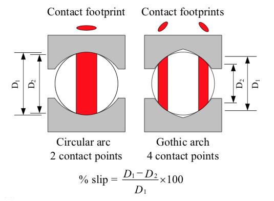
Image credit: Alexander Slocum
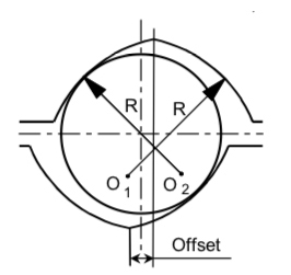
Image credit: NSK
Offset Gothic arch raceway geometry
Some manufacturers use what is referred to as “offset Gothic arch” geometry. The offset Gothic arch design uses four rows of recirculating balls (two on each side of the bearing) in a Gothic arch geometry, but the centers of the top and bottom raceways are offset. This gives the balls two-point contact (similar to the circular arc design).
Under normal loading and low preloads, the top rows of balls sustain the load. But under very high loading, or when there are impact loads, the bottom two rows of balls become engaged and provide additional load-carrying capacity. The offset Gothic arch design provides low friction under normal loading, but under heavier loads and higher preloads, rigidity — and friction — are increased.
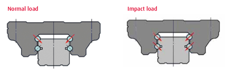
Image credit: NSK


Leave a Reply
You must be logged in to post a comment.