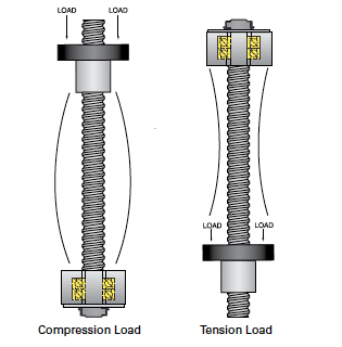
Imagine two columns—one short and wide and the other long and narrow. As you begin to put weight on them, the long, narrow column gradually begins to bend, to the point that it becomes permanently deformed and eventually breaks, while the short, wide column handles the weight with ease.
In the same way the long, narrow column reaches its buckling point earlier than the short, wide column, a long ball screw with a small diameter will deform and buckle under a smaller axial load than a shorter screw with a larger diameter.
Determining the buckling load is an important step in ball screw sizing. The buckling (compressive) load can easily be calculated based on the screw’s root diameter, unsupported length, and end bearing configuration.
where:
Fc = maximum compressive load (N)
fb = end bearing factor
d1 = root diameter of screw (mm)
L = unsupported length (mm)
Application Tip: The end bearing factor, fb, is dependent on the end fixity of the screw. Ball screw manufacturers recommend a safety factor of at least 2 for the maximum applied buckling load, and some incorporate this into this published end bearing factors. To avoid over- or under-sizing, be sure to check whether the manufacturer has built a safety factor into the published fb values.
As shown in the equation, for a given diameter and length ball screw, the permissible buckling load can be increased by changing the support bearing arrangement. The more rigid the support bearings, the higher the bearing factor—ranging from approximately 2.5 for a fixed-free arrangement to 40 for a fixed-fixed arrangement. This means that a fixed-fixed bearing arrangement will result in approximately sixteen times the permissible buckling load than a fixed-free arrangement on the same screw assembly.
In a horizontal application, the axial force is generally equal to the load times the screw assembly’s coefficient of friction, so buckling is typically less problematic than other performance factors, such as critical speed or drive torque. But some horizontal applications, such as pressing and injecting, introduce an additional axial load on the screw assembly, and the buckling load can easily become a constraining factor in screw selection.
When a ball screw is used in a vertical application, it sees the full load as an axial force, which makes buckling a more important concern. Mounting the screw assembly with the most rigid support (typically the fixed bearing) at the top puts the screw in tension rather than compression and counters the effects of the axial load. In the unusual case of a high reversing force—for example, pushing a plunger into a housing on the screw’s upward stroke—the most beneficial bearing arrangement is to orient the fixed bearing at the bottom of the screw assembly.

Image credit: NOOK Industries, Inc.
Application Tip: Most, but not all, screw driven linear actuators use a fixed bearing on the motor side and a floating bearing on the non-driven end. For vertical applications, be sure to check which end of the actuator the fixed bearing is on, in order to avoid excess compressive forces on the screw.
Buckling is a relatively straightforward, but sometimes overlooked, factor in ball screw sizing. The important things to remember are to check the process forces in horizontal applications, and to check the location of the fixed bearing in vertical applications.


In what units is Fc calculated?
I solved Fc=231, will it be pounds or kg, newtons?
Hi Daniel – I apologize, I forgot to put the units on the compressive load, Fc. This is in Newtons, N.