
The rigidity of a ball screw determines the amount of elastic deformation it will experience in the axial direction, under a given load. Elastic deformation, and therefore rigidity, is a fundamental characteristic in selecting and sizing a ball screw, as it affects the positioning accuracy of the system.
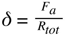
δ = Elastic deformation (μm)
Fa = Applied force in axial direction (N)
Rtot = Rigidity of the screw assembly (N/μm)
In this equation, it’s important to note that the value for rigidity is based on the screw assembly, not simply the screw shaft or the ball nut. A complete screw assembly typically includes the screw shaft, ball nut, support bearings, and housings for the ball nut and bearings—all of which contribute to rigidity.
![]()
Rtot = Rigidity of the screw system (N/μm)
RS = Rigidity of the screw shaft (N/μm)
RN = Rigidity of the ball nut (N/μm)
RB = Rigidity of the support bearings (N/μm)
RH = Rigidity of the ball nut and bearing housings (N/μm)
Rigidity of the ball nut and support bearings are given by their respective manufacturers, while rigidity of the housings depends on their construction and mounting. Besides these components, however, the rigidity of the screw shaft tends to be the lowest of all the components, and based on the inverse nature of the equation, has the biggest influence on total system rigidity.
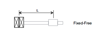
Screw shaft rigidity depends on the end bearing arrangement, the minor diameter of the screw, and the distance between the thrust bearing and the ball nut. For a fixed-free or fixed-floating arrangement, the screw shaft rigidity is calculated as follows:
![]()
![]()
A = Cross-sectional area of the screw (mm2)
d1 = Minor diameter of the screw (mm)
E = Modulus of elasticity of steel (2.06 x 10⁵ N/mm)
L = Distance between the ball nut and the fixed bearing (mm)
When the end bearing arrangement includes two fixed ends, the rigidity of the screw shaft takes into account the distance of the ball nut from each of the fixed end bearings.
![]()
La = Distance between the ball nut and one fixed bearing (mm)
Lb = Distance between the ball nut and the other fixed bearing (mm)
In the fixed-fixed arrangement, the rigidity will be lowest when the ball nut is located halfway between the two fixed ends, with La = Lb = L/2. The rigidity equation then becomes:
![]()

The equations show that rigidity is four times higher for screw assemblies with fixed-fixed mounting than for those with fixed-free (or fixed-floating) mounting, so the end bearing configuration is the first thing to consider if a screw assembly is not rigid enough for the application. Another method to improve rigidity is to use a larger diameter screw. This increases not only the rigidity of the screw shaft, but also of the ball nut and, in most cases, of the end bearings.
Conversely, increasing the preload of the ball nut generally has only a small effect on rigidity, since the ball nut is a minor factor in the total system rigidity. Increasing preload also has the potentially detrimental effect of higher frictional torque, more heat generation, and greater material expansion of the screw shaft.
Featured image credit: Nook Industries

Leave a Reply
You must be logged in to post a comment.