

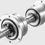
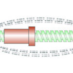
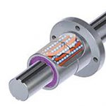
A ball spline is much like a linear ball bushing and shaft, but with axial grooves along the outer diameter of the shaft and the inner diameter of the nut. These grooves prevent rotation of the bearing (referred to as a spline nut) and allow the ball spline to transmit torque.
Because a ball spline has this unique ability to withstand both radial and torque loads, both loading conditions need to be analyzed when determining bearing life.
Since the load-bearing elements for both loading cases (radial and torque loads) are balls, the familiar bearing life equation can be used.
For a ball spline with radial loading, the bearing life is calculated as:
![]()
L = rated bearing life (m)
C = dynamic load rating (N)
P = applied radial load (N)
For a ball spline with torque loading, the bearing life is calculated in a similar way, but using the ball spline’s rated torque capacity and the applied torque load:

CT = dynamic torque rating (Nm)
T = applied torque (Nm)
Note that the life equations shown above are based on a life of 50,000 m (50 km). To convert these life ratings to a basis of 100,000 m (100 km), divide the 50,000 m ratings by 1.26, as explained here.
Like linear ball bushings, spline shafts sometimes encounter conditions that can adversely affect the bearing life, so the bearing life equation typically includes correction factors for shaft hardness, operating temperature, contact (to account for uneven loading when more than one spline nut is used on the same shaft), and shock and vibration loads.
These factors are often combined into a single “modification” factor:
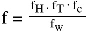
f = combined modification factor
fH = shaft hardness factor (typically ranges from 0.5 to 1.0)
fT = temperature factor (typically ranges from 0.9 to 1.0)
fC = contact factor (typically ranges from 0.72 to 1.0)
fW = load factor for shocks and vibrations (typically ranges from 1.0 to 2.5)
With the correction factors, the life calculations become:
For radial loading:
![]()
For torque loading:

Note that the life calculations shown above assume that the radial and torque loads are applied in separate instances. If both radial and torque loads are applied simultaneously, the torque load should be converted to an equivalent radial load.
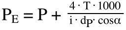
PE = equivalent radial load
i = number of rows under load
dp = ball circle diameter (mm)
cosα = contact angle
It’s important to note that this conversion is based on the number of rows that are under load, the diameter of the ball centers on the spline shaft, and the angle of contact, all of which depend on the unique geometry of each spline shaft and nut assembly, so these values must be provided by the manufacturer.

Image credit: TBI Motion
With the equivalent radial load determined, the life equation for a ball spline with simultaneous radial and torque loading is given as:

 Feature image credit: Nippon Bearing

Leave a Reply
You must be logged in to post a comment.