
Profiled linear guides—whether profiled rails, cam roller guides, shaft support rails, or plain bearing guides—are typically manufactured with evenly spaced mounting holes that allow them to be secured to a machine base or work surface. For rigidity and integrity of the rail, there’s often a minimum distance, specified by the manufacturer, that must be maintained from the end of the rail to the center of the first hole. And if rail sections are joined (aka “butted” or “butt-jointed”), the distance between holes at the joined ends should be equal to the spacing between all other holes.
All of these requirements can make figuring out the appropriate rail length and hole spacing seem like an indeterminate algebra problem. But if you think about the rail in terms of its number of holes and the spaces between the holes, it becomes easier to visualize the layout and to calculate the appropriate rail length to meet the hole spacing (aka pitch) and end distance specifications.
Regardless of the rail length, you should always check the manufacturer’s catalog to find out the pitch of the mounting holes and the minimum distance from the end of the rail to the center of the first hole. Hole spacing among same-sized rails is somewhat standard between manufacturers, but a few suppliers and rail styles deviate from the standard.

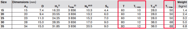
To figure out if the required rail length allows the proper dimension between the end of the rail and the center of the first hole, first divide the rail length by the hole pitch. For example, let’s take a size 25 profiled rail with a required length of 1270 mm.
For the size 25 rail, the hole pitch is 60 mm.
1270 ÷ 60 = 21.167
The integer (whole) part of the result tells us the number of complete spaces in the rail. In this case, there are 21 spaces, which means there are 22 holes. The remainder indicates how many millimeters are available on both ends of the rail combined. In this example, there is 0.167 of a complete pitch (60 mm) remaining, which equals 10 mm.
0.167 x 60 = 10
Again, this 10 mm is for both ends of the rail combined, so there will be 5 mm from the center of the last hole to the end of the rail on each end.
For the size 25 rail, the minimum distance allowed at the end is 10 mm, but only 5 mm is available. This is important because using a rail with less than the minimum distance at the ends can result in higher stresses, less holding force, and even failure of those last holes.
Solution #1: Increase the rail length
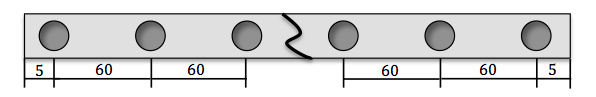
To remedy this situation, the easiest option is to add 10 mm to the length of the rail (5 mm for each end), making the rail length 1280 mm instead of 1270 mm. Let’s check that this will be sufficient:
1280 ÷ 60 = 21.333
0.333 x 60 = 20
This gives us 10 mm from the center of the last mounting hole to the end of the rail, on each end, which meets the minimum requirement.

Solution #2: Take away a mounting hole
If increasing the rail length is not feasible, an alternative is to keep the rail length the same, but cannibalize one hole pitch and add half its value to each end.
Keeping our original rail length of 1270 mm, we’ll use 20 spaces (21 holes), instead of 21 spaces (22 holes). To check the end dimensions, let’s look at how many millimeters of length the 20 spaces will take up:
20 x 60 = 1200
1270 – 1200 = 70
This leaves 70 mm to be divided between each end of the rail, or 35 mm on each end, which is is well above the minimum requirement of 10 mm and still below the maximum of 50 mm.

Like the minimum distance at the end of the rail, there is also a maximum distance that must be taken into account. If the maximum distance is exceeded, the end of the rail will “cut into” what would be the next hole, due to the diameter of the hole—particularly if the hole is drilled for a countersunk screw. For example, if the hole spacing is 60 mm and the countersink diameter is 10 mm, then at an end distance of 55 mm, the cut will intersect the bore for the screw. Manufacturers typically add several millimeters of safety to protect the integrity of the material at the end of the rail, so the published maximum distance will be closer to 50 mm.
Solution #3: Reduce the rail length
Another method to get an acceptable end dimension is to reduce the length of the rail by one-half of a hole pitch (30 mm) and allocate the remaining one-half pitch to each end of the rail. Here’s how that works mathematically:
1270 – 30 = 1240
1240 ÷ 60 = 20.667
0.667 x 60 = 40
This means that the rail will now have 20 spaces (21 holes), with a remainder of 40 mm, or 20 mm on each end. In other words, the one-half hole pitch (30 mm) has been added to the original remainder of 10 mm, giving 40 mm to be divided between the two rail ends. This gives each end has a distance of 20 mm instead of 5 mm.
Feature image credit: kenopoolgame.com

Leave a Reply
You must be logged in to post a comment.