
The standard life calculation for linear ball bearings is widely known as:
![]()
L = bearing life (m)
C = rated dynamic load (N)
F = applied dynamic load (N)
But linear ball bushings often experience operating conditions that aren’t accounted for in the general bearing life equation. To account for these adverse conditions, the life calculation for linear ball bushings includes a number of correction factors that adjust the bearing life accordingly.
![]() Here, we’ll look at each of these correction factors and explain how and when to use them.
Here, we’ll look at each of these correction factors and explain how and when to use them.
Load orientation
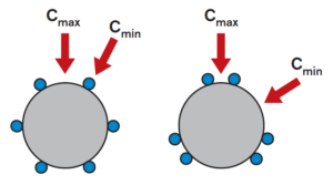
Image credit: Bosch Rexroth
The first correction factor (KΘ) accounts for the orientation of the load relative to the ball tracks, or circuits, in the linear bushing. When a load is applied to a linear bushing assembly, the orientation of the bushing on the shaft and the direction of loading determine whether the load is carried by just one ball track or shared between two or more tracks.
To account for this variability, manufacturers offer charts or polar graphs that provide load correction factors depending on the orientation of the load relative to the orientation of the ball tracks.
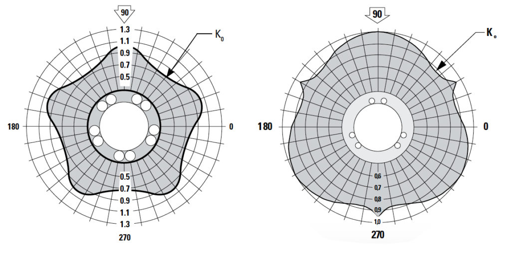
Image credit: Thomson Linear
Unlike other correction factors, the load correction factor can be greater than 1.0 in some cases, meaning that a specific load-bushing orientation provides a dynamic load capacity that is higher than the published value.
Shaft hardness
In a recent article, we looked at how the hardness of the shaft can affect the life of a linear bushing assembly. Manufacturers typically recommend that shafts used with linear ball bushings have a hardness of 58 to 60 HRC. If the shaft hardness is lower than recommended, a shaft hardness factor (KS) must be applied to de-rate the bearing’s dynamic load capacity, and in turn, the bearing’s expected life.
Temperature
Very high operating temperatures can affect the integrity of the components that make up the bushing — such as seals and load plates — and can also reduce the shaft hardness. A temperature correction factor (KT) takes into account this degradation in material and typically comes into play for operating temperatures above 100° C.
Short stroke
When the stroke of a linear ball bushing is very short — between 1.5 and 3 times the length of the bushing, depending on the manufacturer and bearing type — the application is often considered a “short stroke” application. In these conditions, the shaft may experience accelerated wear and premature failure, since a small area of the shaft must continually withstand the forces and pressure created by the load-carrying balls. The short-stroke factor (KC) takes this into account and reduces the bearing life accordingly.
Life factor
The bearing life equation determines the expected life of linear ball bushing for a given dynamic load capacity and applied dynamic load. But in some cases, the desired bearing life and the applied load are known, and the parameter to be calculated is the required dynamic load capacity of the bushing that will provide the specified bearing life under the given load. In this case, the required dynamic load capacity (CR) is calculated as follows:
![]()
But recall that the bearing life for a linear ball bushing is based on 100,000 m (or 2 million inches for inch products). If the desired bearing life is greater than 100,000 m (or 2 million inches), the applied load must be divided by a life factor (KL) in order to account for the longer bearing life.
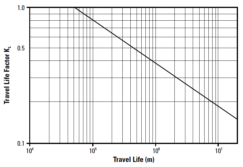
If you’re dealing with metric linear ball bushings, don’t forget to check whether the bearing is rated for 50,000 m or 100,000 m of life and apply the appropriate correction factor when making comparisons between bearings with different life ratings.

Leave a Reply
You must be logged in to post a comment.