
When choosing a recirculating linear guide, one of the key criteria in the specification is preload. Linear guide preload eliminates the clearance between the bearing block and the rail, which increases rigidity and reduces deflection when external loads are applied.
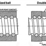
To achieve preload, manufacturers use balls (or rollers, in the case of roller bearings) whose diameter is slightly larger than the distance between the raceways of the block and the rail. The preload of a linear bearing block is given as the percentage of dynamic load capacity that is induced on the bearing, with common preload amounts being 2, 5, and 8 percent. For example, a bearing block with a dynamic load capacity of 30,000 N and a preload of 5 percent would experience a preload force of 1500 N. For roller bearing guides, which are typically used for extremely high loads and/or minimal deflection, preload amounts up to 13 percent are available.
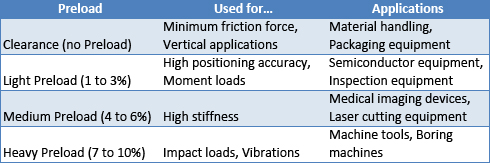
When selecting a profiled linear guide, it may seem logical to choose a high preload, because, in most applications, the less deflection there is, the more accurate the assembly will be. But bearing preload comes with tradeoffs, so it’s best to choose the preload based on the application requirements rather than using a higher preload than necessary. Here are the main factors to consider when selecting linear guide preload.
Positioning accuracy
A linear guide without preload (often referred to as “clearance,” since there is clearance between the raceways of the bearing block and the rail) allows some play in the motion, which can negatively affect positioning accuracy. For applications where the positional accuracy is important, such as assembly and dispensing, a linear guide with light preload (2 percent) is generally recommended. A higher preload doesn’t necessarily provide better positioning accuracy, unless deflection becomes a factor.
Deflection
The more rigid, or stiff, a linear guide is, the less deflection it will experience. And even a small deflection at the bearing block will be amplified at the end of arm tooling. This makes preload an important factor in applications where the tooling or working area is located far from the linear guide assembly. Machine tools, for example, often have to move heavy loads that are positioned a long distance from the bearing blocks. In applications such as this, where high rigidity and low deflection are needed in order to accurately process parts, a heavier preload of 5 to 8 percent is often necessary.
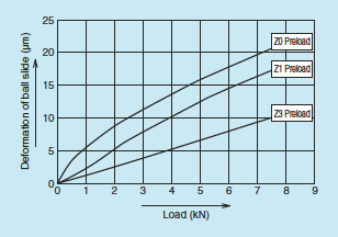
Image credit: NSK Ltd.
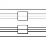
Linear guide layout
Profiled linear guides are frequently used in configurations having two profiled rails in parallel and two bearing blocks per rail, creating a square or rectangular pattern. This arrangement provides the best support for moment loads in the roll, pitch, and yaw directions. And while alignment of multiple rails and bearing blocks is always important, if the bearings are preloaded, alignment becomes even more critical.
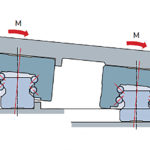
Case in point: when two profiled rails are used in parallel, with carriages that are preloaded, the permissible offset in the vertical direction (typically denoted S1) is smaller than if the carriages were not preloaded. If the maximum vertical offset is exceeded, a roll moment will be introduced into the bearing blocks, which can reduce bearing life. So while higher preload can reduce deflection and provide better positioning accuracy, it also requires more precise machining of the mounting surface.
In addition to mounting considerations, there are several reasons why you should use the lowest preload that will work for your application.
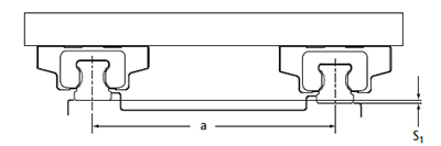
Image credit Thomson Industries, Inc.
More is not always better
First, preload creates an internal force on the bearing that acts as a static force, similar to an applied static load. This preload force must be accounted for in static load and bearing life calculations, in addition to the applied load. (However, the internal force is counteracted as an external load is applied. For most linear bearings, the preload force can be disregarded in bearing life and static load calculations when the applied load is equal to or greater than 2.8 times the preload force.)
Also, preload increases the force required to move the bearing block, which can dictate the use of a larger motor and related components. And higher preload causes more heat to be generated inside the bearing block, which increases wear and reduces life.
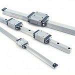
Feature image credit: Bosch Rexroth Corporation


Leave a Reply
You must be logged in to post a comment.