
Updated May 2019 || Ball screw rigidity depends not only on the screw shaft and ball nut, but also on the thrust bearings and on the ball nut and bearing housings.

Where:
Rtot = Rigidity of the screw system (N/μm)
RS = Rigidity of the screw shaft (N/μm)
RN = Rigidity of the ball nut (N/μm)
RB = Rigidity of the support bearings (N/μm)
RH = Rigidity of the ball nut and bearing housings (N/μm)
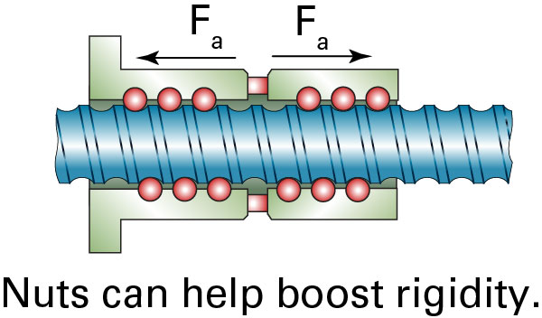
The default method for increasing ball screw rigidity is to increase the preload of the ball nut. 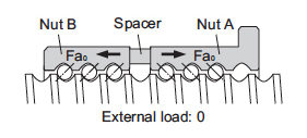 However, the ball nut is one of the most rigid components in the ball screw assembly, so increasing ball nut rigidity has little effect on the overall system rigidity (except when upgrading from a ball nut with no preload to one that is preloaded). Also, higher preload causes higher frictional torque, which means more heat is generated and more torque is required to drive the screw. A double ball nut is somewhat more rigid than a single nut, but again, the effect is minimal due to the nut’s already high rigidity relative to the other components.
The limiting factor for rigidity in a ball screw assembly is typically the screw shaft. The rigidity of the screw shaft depends on its modulus of elasticity, diameter (which determines its cross-sectional area), and unsupported length.
The screw’s modulus of elasticity is dependent on the material (typically steel), and its diameter is primarily determined by the required thrust force and speed. The unsupported length of the screw shaft is determined by the stroke and the end bearing arrangement.
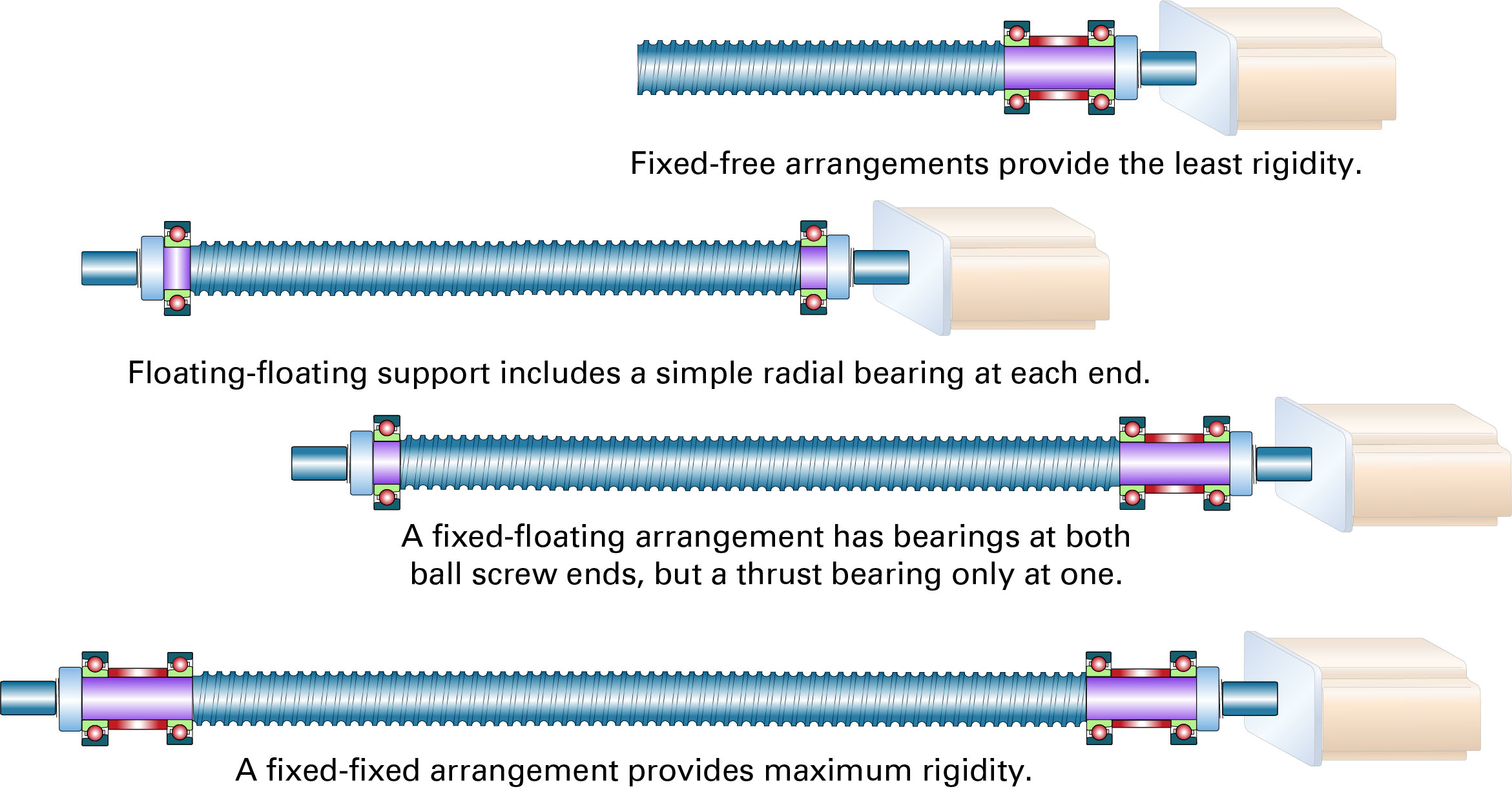
While the screw’s material and diameter are generally set by the application, the end bearing arrangement (and hence, its influence on unsupported length) is chosen based on factors such as speed, buckling load, and rigidity.
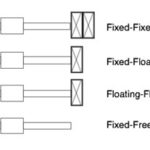
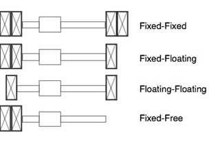 There are four common end bearing combinations for ball screw assemblies. From most to least rigid, they are: fixed-fixed, fixed-floating, floating-floating, and fixed-free.
A fixed end uses an angular contact thrust bearing, for support against both radial and axial loads, while a floating end uses a simple radial bearing, with no support for axial loads.
A free end has no bearing support.
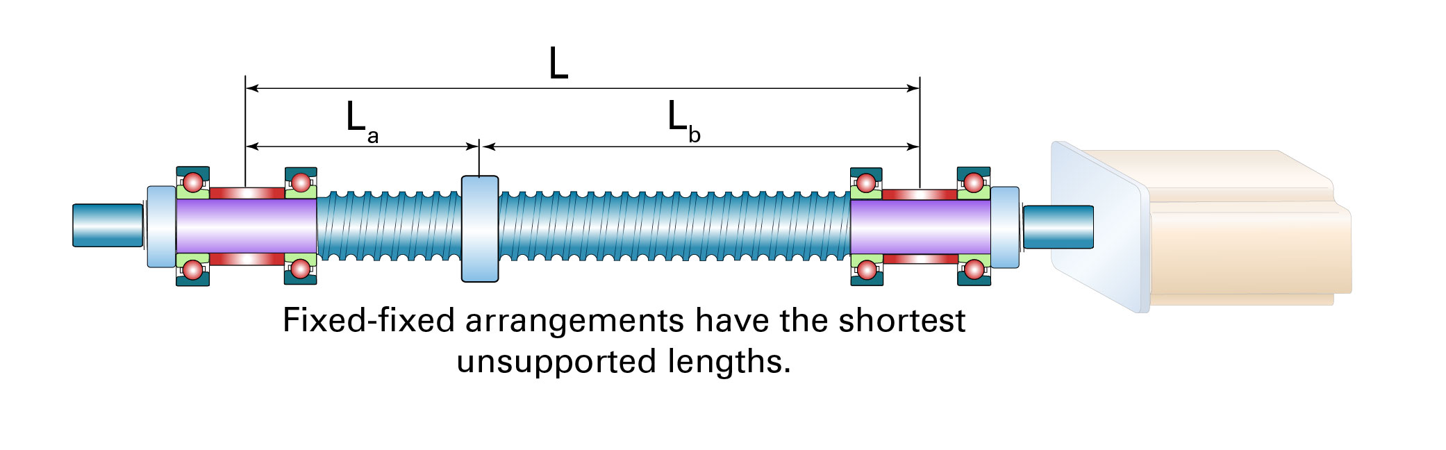
Using the stiffest bearing arrangement – fixed-fixed – increases the rigidity of the screw shaft by four times compared to the least rigid arrangement of fixed-free. This is due to two design advantages.
First, using angular thrust bearings on both ends allows forces to be transmitted through the screw on both sides of the ball nut. 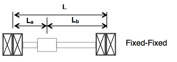
In addition, with thrust bearings on both ends, the maximum distance between the ball nut and either one of the fixed bearings occurs when the nut is at the middle of the stroke, which means the unsupported length is one-half the length of the screw.
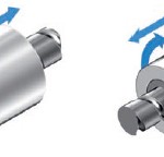
Another effective method to increase ball screw rigidity is to change the way the assembly operates: hold the screw stationary and rotate the ball nut. In a rotating nut design, because the screw itself does not rotate, there is no need for support bearings on the ends of the screw shaft. Instead, the ball nut is supported by a large angular contact thrust bearing. The screw shaft is rigidly mounted at both ends, which allows torsional moments to be transmitted to the mounts at each end of the screw. While a rotating nut assembly is very rigid, its construction can pose dimensional problems and interference issues for applications that were designed with standard rotating screw assemblies in mind.
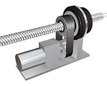
Image credit: SKF Group
Feature image credit: Bosch Rexroth Corporation


Leave a Reply
You must be logged in to post a comment.