
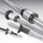
Linear actuators come in a wide range of sizes, and over the past several yeas, manufacturers have been emphasizing more and more compact footprints. But no matter how small the actuator, the addition of a motor can make the overall size of the complete system too large for space-constrained applications. Some manufacturers are addressing this issue by integrating a motor and a lead screw (or ball screw) into one assembly, in what are commonly referred to as hybrid actuators.
The most common variation of the hybrid design is a stepper motor with an integrated lead screw, since the two components have similar specifications for load, speed, and thrust force. And this is arguably where the integrated layout provides the greatest benefit, since the loads and forces required in lead screw applications are typically smaller and better suited for a design without external guidance (i.e. no linear shafts or rails to support the load). However, guides can be integrated into hybrid actuators, giving them greater versatility for use in applications such as precision positioning systems, where a load needs to be supported as it’s moved.
Hybrid actuators are also available in designs that combine a ball screw with a stepper motor or a ball screw with a servo motor. The use of a ball screw rather than a lead screw provides better efficiency and higher thrust forces. And when combined with a servo motor, higher positioning accuracy can be obtained through closed-loop servo control.

Note that it’s rare to see an integrated design that incorporates a lead screw with a servo motor, since the lead screw’s positioning accuracy is typically not high enough to justify the cost and complexity associated with using servo control.
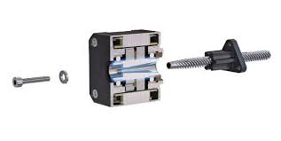
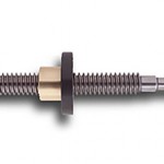
The basis of a hybrid actuator is a hollow shaft motor. Instead of the common motor design, which includes a simple drive shaft running through the center of the rotor, the screw shaft or the screw nut is mounted inside the rotor. When the screw shaft is mounted inside the rotor, the configuration is sometimes referred to as a driven screw assembly, and when the screw nut is mounted inside the rotor, the configuration is commonly referred to as a driven nut assembly.
The driven screw configuration is most similar to a traditional screw assembly in terms of end fixity, where one end of the screw is supported by one or two axial bearings and coupled to the motor, while the opposite end is either “free” (not supported) or supported by one or two axial bearings. The difference in a driven screw hybrid actuator is that the driven end of the screw is mounted directly into the rotor of the motor and is supported by bearings inside the rotor. No external bearings or screw-to-motor coupling are needed. Like a traditional screw assembly, the nut is mounted external to the motor, and the rotation of the screw moves the nut along the screw shaft.
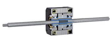
In the driven nut configuration, movement can occur in one of two ways: the nut/motor combination can be constrained so that the screw shaft travels back-and-forth as the motor rotates the nut; or the screw shaft can be constrained so that the motor/nut assembly moves along the stationary screw. When the screw shaft is constrained and not allowed to rotate, higher speeds can typically be achieved, since “whipping” (the jump-rope type effect that occurs when a screw is turned very rapidly) is avoided. An axial bearing is typically mounted on the outer circumference of the screw nut (inside the motor rotor) in order to take up thrust forces.
Along with the benefit of compact size, having fewer mechanical connections can reduce overall system compliance, when compared to similar systems that incorporate a motor externally coupled to a screw. In systems without linear guides, the main areas of application for hybrid actuators involve pushing or pulling relatively light loads, or precise positioning, such as in focusing and scanning applications. When linear guides are incorporated, hybrid actuator systems provide a very compact solution for X-Y stages and small machining centers, such as 3D printers.
Feature image credit: Disney

Leave a Reply
You must be logged in to post a comment.