
In linear motion applications, ball screws are widely recognized for their ability to provide high thrust forces, while linear motors are gaining market share in high-speed applications, and belt drives continue to maintain their reputation as the best solution for long travel lengths. But rack and pinion drives are the often-overlooked workhorses behind gantry and transport applications that require long travel, high acceleration rates, and high thrust forces at a relatively low cost — a performance-price combination the other drive technologies have difficulty achieving.
While the rack and pinion drive is sometimes dismissed as old technology, a look at the market for linear motion solutions demonstrates that this isn’t the case. In fact, manufacturers of linear actuators commonly offer rack and pinion drive versions, and several profiled rail guide manufacturers offer integrated rack and pinion systems, with the rack ground into the guide rail profile or the guide rail mounted directly on the rack.
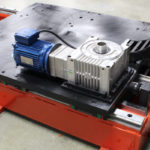
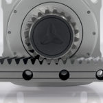
Further evidence that rack and pinion drives aren’t going away is the investment that manufacturers continue to make in the technology — from developing improved methods for tooth grinding to researching new materials with better hardness and surface finish for reduced wear, higher efficiency, and reduced weight.
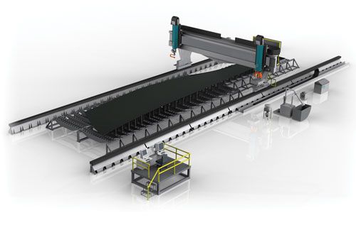
Image credit: Atlanta Drive Systems, Inc.
This is good news for designers and engineers who are faced with applications that require any combination of long stroke, high thrust force, high speed, and challenging environmental conditions. And compared to other linear drive options, rack and pinion drives are relatively simple to select, integrate, and operate.
Case in point: Unlike ball screw sizing — which must take into account factors such as characteristic and critical speeds, end bearing considerations, and the effects of preload, in addition to basic thrust force and drive torque calculations — rack and pinion drive sizing is primarily based on three factors: the force the rack sees (referred to as the “feed force” or “tangential force”), the torque the pinion sees, and the rotational speed of the pinion.
Tangential force on the rack: horizontal application
In a horizontal application, the rack experiences two forces due to the movement of the mass: a force created due to the moved mass acting against the coefficient of friction of the guide rails, plus a force that results from accelerating the mass. In addition, if the application involves any external pressing forces, those are included in the tangential force calculation.
![]()
Fr = force on rack (N, lbf)
m = moved mass; includes the application load, plus any system components that are being moved, such as the pinion, gearbox, motor, etc. (kg, lbm)
g = gravitational constant (9.81 m/s2, 32.2 ft/s2)
μ = coefficient of friction of guide mechanism (typically 0.002 to 0.003 for ball or roller recirculating guides)
a = maximum acceleration the system will experience (m/s2, ft/s2)
Fe = pressing force due to the application; if applicable (N, lbf)
Tangential force on the rack: vertical application
In a vertical application, the load moves in the direction of the guide system, so the force due to the moved mass is not affected by the coefficient of friction of the guide rails.
![]()
Torque on the pinion
The torque on the pinion is simply the tangential force (force on the rack) multiplied by the pinion radius.
![]()
 Tp = torque on pinion (Nm, ft-lb)
rp = pinion radius (m, ft)
Remember to divide the pinion diameter by 2 to get the radius, and by 1000 to convert from mm to m (or by 12 to convert from inches to feet).
![]()
dp = pinion diameter (mm, in)
Maximum rotational speed of pinion
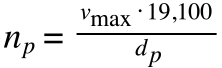
To determine the maximum rotational speed of the pinion, simply divide the maximum linear speed of the application by the pinion circumference (π * diameter), convert from millimeters to meters, and convert from seconds (linear speed, m/s or ft/s) to minutes (rotational speed, rpm) .

np = maximum rotational speed of pinion (rpm)
vmax = maximum linear speed of application (m/s, ft/s)
This equation is sometimes simplified as:
It’s important to note that rack and pinion manufacturers recommend using various “correction” factors when determining the force on the rack. The most common are a typical safety factor and a service factor (sometimes referred to as a “load factor” or “operation mode factor”), which is determined by the level of shock loads the rack and pinion drive could encounter. Some manufacturers also recommend taking into account a life factor, depending on the pinion speed and the frequency of lubrication (continuous, daily, or monthly).
In addition to mechanical sizing, selecting a suitable rack and pinion drive for an application also includes determining the required gear quality, surface treatment, and hardness. While surface treatment and hardness are relatively straightforward, gear quality is a classification system that specifies allowable values for gear flank tolerances (which play a significant role in positioning accuracy and in the smoothness of velocity and force production). Gear quality is defined in several standards, including ANSI/AGMA standard 2015-2 and ISO standard 1328-1.


I did not understand the pressing force. Would it be the force to turn the steering wheel in a car, for example? Isn’t it considered already in the tangencial force?
Thank you so much for easier explanation.
But Still I have few clarifications on these
1. What about Transmission efficiency
2. Safety Factor – whether it should be considered, if yes then how much to be considered for different type of applications.