
In a previous motion-sizing article, we reviewed how to properly specify a ballscrew-driven motion axis. Here we review how engineering teams can use a similar approach for sizing rack-and-pinion-based servomotor-driven axes on the same five-axis gantry. We’ll use manufacturer software to work through the application.
By Sixto Moralez • Regional motion engineer | Yaskawa America Inc.
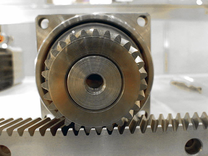
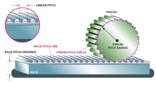
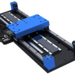
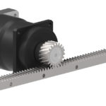
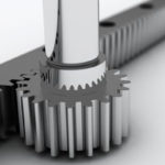
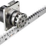
Rack-and-pinion mechanisms include a circular gear (the pinion) typically made of steel with equally spaced teeth. This pinion engages a linear gear (the rack) to convert rotational motion into translational motion. A servomotor directly drives the pinion to either cause the servomotor-pinion assembly (and attached loads) to travel along the rack or (less commonly) to cause the rack (and attached loads) to advance and retract.
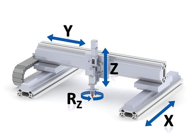
So assume the Z axes (Z and Z prime) are ballscrew mechanisms sized with the approach we detailed in our last installment. (Visit linearmotiontips.com and search Sixto for this article.) Also assume our design’s axes X and Y (Y and Y prime) are rack-and-pinion mechanisms.
With such multi-axis systems, the easiest approach is to start the sizing at the smallest or most distal axes (in this case, our X axis) because these axes’ overall weight and any masses they bear will be part of the payload for the system’s larger upstream axes (here, Y and Y-prime). So, let’s start with the X axis.
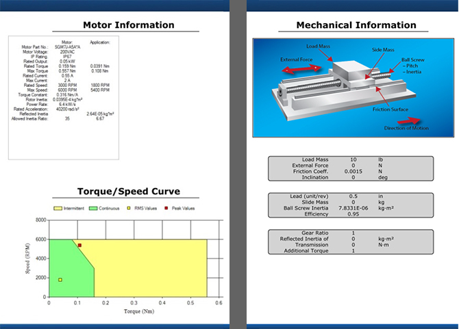
Payload is a 30-lb tool that must move side to side along the rack. The fastest speeds reach 20 feet per minute. Currently the system doesn’t have the torque needed for the move. Thus proper sizing is critical to ensure the new servomotor will be able to move and control the load on the rack system.
First step: Entering data in sizing software
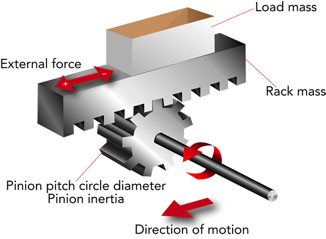
We use a step-by-step approach to entering data into our motor and drive manufacturer software, about the Rack-and-pinion system to have the ability to select a servomotor. Let’s begin with the Pinion. Questions to ask are:
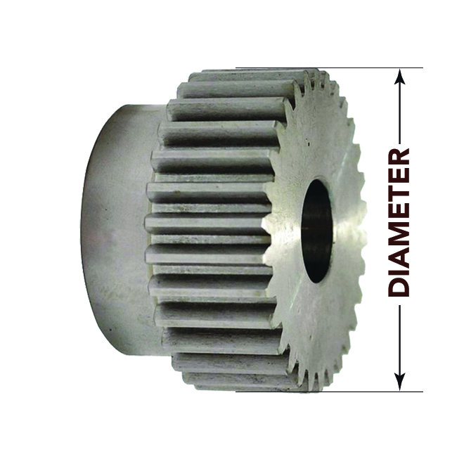
What is the diameter of the pinion? Is the measurement in millimeters or inches? Assume our pinion is 3 inches in diameter. We will use this to determine the circumference of the pinion for distance travelled.
Who is the pinion manufacturer? HDK? TSK Machinery & Engineering? WITTENSTEIN?
What is the thickness of the pinion? What is its width? Assume for our example our pinion is 1 in. wide.
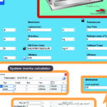
What is the density of material? Pinions are often manufactured of steel, but some are made of aluminum. If unsure of the pinion’s material, some software includes a calculator to closely estimate the material composition that factors into its inertia.
What is the pinion’s pitch-circle diameter (PCD)? Generally, the PCD of a pinion is defined by its outer diameter.
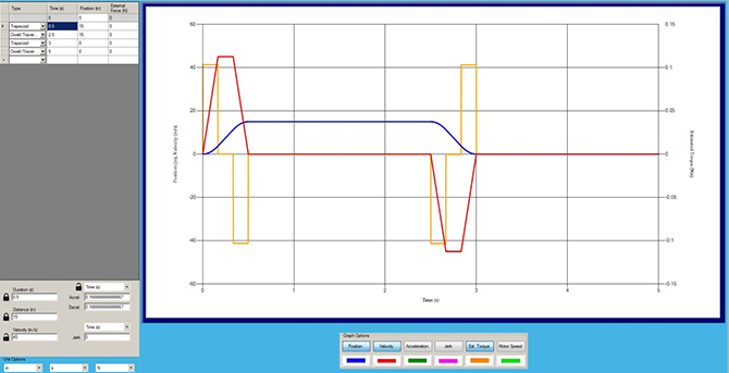
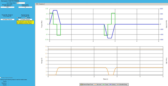
Calculating the move profile
The move profile of a rack-and-pinion axis is calculated in terms of linear distance. To get a safe move profile estimate, it’s always best to use stroke and acceleration values associated with a worst-case scenario. As previously stated, the maximum speed for our example 3D-printing application will be 20 feet per minute and the end user would like the axis to execute this speed within one minute.
Here, it’s easiest to enter anticipated move values in the software (in metric or U.S. standard units) to calculate the worst-case move profile. That’s because within design software, modifications to the acceleration ramps can be adjusted by Accel and Decel entries — as well as the type of units to use.
Design tip: Use pauses or dwells at the end of each move and a return move to start at the beginning.
Servomotor and gear selection within software
To reiterate — choosing a servomotor for an application needn’t be tedious. Selection software accepts data about a given axis’ parameters to yield one or more servomotor options to satisfy the application. In fact, some manufacturers’ design software integrates with digital catalogs to provide specific recommendations. That’s particularly useful for the final selection of servomotors — as each series and model can have unique advantages and limitations.
For our rack-and-pinion axis, software will recommend low-inertia servomotors for small capacity applications.
Some software will also recommend the inclusion or omission of a gearbox — usually with industry-standard 3:1, 5:1, 10:1, 15:1, and 20:1 ratios. Where partnerships support it, final recommendations can take the form of fully integrated gearmotors. If ratios or gearbox types presented aren’t optimized to the design, particularly flexible software will allow the manual entry of third-party gearbox specifications. These values include the gearbox ratio, inertia, and efficiency.
For example, adding a 3:1 gearbox to the servomotor for our application will actually let us choose a slightly smaller gearbox — a 200-Watt version instead a 400-W version — for an upfront motor cost that is 25% lower.
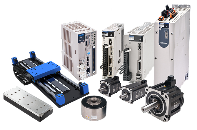
More specifically, it identifies the SGM7J-04A 400-Watt servomotor (accepting three-phase 200 Vac input) as the best match for the parameters we’ve set. If the application requires more speed but not a lot of torque, Yaskawa SGM7J or SGM7A-series motors maybe more suitable. Conversely, if the application requires more torque and not a lot of speed, SGM7G-series motors may be best. Where an application has dimensional constraints, SGM7P-series may be necessary. For a full list of servomotors from this line, visit www.yaskawa.com/products/motion/sigma-7-servo-products.
Regeneration, connectivity, and reports
Advanced servo-design software will indicate if a regenerative resistor is needed and what capacity should be selected. For more information on regeneration, please visit motioncontroltips.com and search: Don’t forget these two things when selecting an amplifier.
Additional drive parameters to be entered include the power input and drive type — as well as any requirements for analog pulse control as well as EtherCAT or Mechatrolink-III connectivity, for example.
Look for servomotor selection software that can do the above and deliver full design reports to share with end users for machine-performance verification.
Yaskawa America Inc. | yaskawa.com/products/motion/sigma-7-servo-products

Leave a Reply
You must be logged in to post a comment.