
When designing a belt drive system, the first step is to choose the most suitable belt for the application. But the pulleys also play an important role in the performance of the belt — especially in synchronous belt drive systems, where proper meshing of the belt teeth with the pulley grooves can affect everything from the amount of torque that can be transmitted to the belt’s rate of wear and potential failure modes.
Synchronous belt and timing pulleys are typically designated by the number of grooves (analogous to the number of teeth on the belt), groove pitch (analogous to the belt tooth pitch), and pulley width.
The required tooth pitch (and, therefore, groove pitch) is determined during belt selection, based on the design torque and speed. Torque and speed are also the primary factors in determining belt width, and, therefore pulley width. (Recommended pulley width is typically slightly larger than the belt width and takes into account the space required for pulley flanges.) The number of pulley grooves is determined by the required speed ratio.
Dimensional information also includes the type and size of hub for attaching the pulley to the drive shaft. Common options for pulley mounting include taper lock bushings, split taper bushings, QD (quick disconnect) bushings, or plain bores with or without keyways.
Although pulley diameter isn’t explicitly specified during selection, it can be determined by the number of pulley grooves and their pitch, which are used to calculate the pitch diameter of the pulley. The pitch diameter is slightly larger than the outer diameter of the pulley and corresponds to the pitch line of the belt, which is the line formed by the belt’s tensile cord.
![]()
pd = pulley pitch diameter (mm, in)
P = pulley groove pitch (also belt tooth pitch) (mm, in)
N = number of pulley grooves
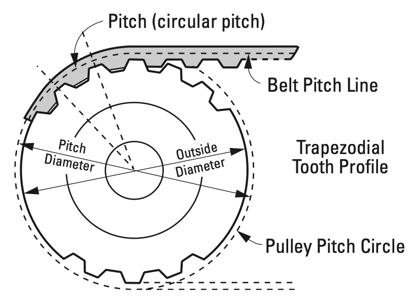
Image credit: Pfeifer Industries
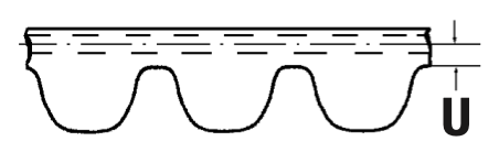
Once the pitch diameter is calculated, the pulley’s outer diameter can be determined by finding the distance from the belt pitch line to the bottom of the tooth profile (a value specified by the belt manufacturer), and subtracting twice that distance from the pulley pitch diameter.
![]()
O.D. = pulley outer diameter (mm, in)
U = distance from belt pitch line to bottom of tooth profile (mm, in)
Some manufacturers offer pulleys in the form of bar stock, to be cut and machined by the user. While this can be an economical solution for prototyping small quantities, the accuracy of the pulley is critical to ensure proper belt tracking, speed ratio, and efficiency.
Acceptable pulley tolerances are specified by trade associations (such as the Mechanical Power Transmission Association, MPTA) and by the International Standards Organization (ISO). In some cases, major belt manufacturers also specify tolerances for specific tooth profiles.
Key manufacturing tolerances for synchronous belt pulleys include:
- pulley outer diameter
- eccentricity between pulley bore and pulley outer diameter
- parallelism between pulley bore and vertical faces of the pulley
- pitch accuracy of grooves
- parallelism between grooves and bore.
It’s important to note that pulleys may also need to undergo static or dynamic balancing after manufacturing.
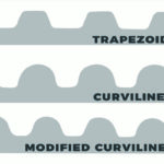
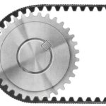
Synchronous belt pulleys can be made from a wide range of materials, including aluminum, steel, cast iron, and various plastics. The material of the pulley determines its weight and inertia, and so affects the dynamic performance of the belt drive system. Material selection also influences the amount of noise generated by the system, with polycarbonate (thermoplastic polymer) pulleys generating more noise during operation than metal pulleys.
Image credit: Brecoflex Co., LLC
To prevent the belt from riding off the pulley, and to resist the lateral forces caused by the belt’s side-to-side motion, synchronous belt drives typically require flanged pulleys. In general, manufacturers recommend that synchronous belt systems include at least one pulley with flanges, although there are exceptions to these guidelines, as noted in this article on pulley flanges.

Leave a Reply
You must be logged in to post a comment.