
Image credit: Kollmorgen
Servo motors are typically used for dynamic applications, where quick acceleration rates necessitate high torque production. In fact, one of the defining characteristics of a servo system is its ability to precisely control torque across a wide speed range, and the various speeds and torques required during the application’s move profile are a key parameter for sizing and selecting a servo motor.
To help designers and engineers evaluate the motor’s capabilities and compare them to the application requirements, manufacturers publish torque-speed curves for specific servo motor and drive combinations.
Although many factors contribute to the development of the torque-speed curve, one of the most important is motor heating. The main risk of operating outside the continuous or intermittent duty zone is thermal damage. And because voltage and current supplied by the drive affect the amount of heat produced by the motor, torque-speed curves are based on specific motor-drive combinations. Using a different servo drive can change the motor’s torque-speed curve.
A servo motor’s torque-speed curve includes two operating zones: continuous duty and intermittent duty. To choose a motor that can meet the application requirements, it’s important to ensure the application runs within the continuous duty zone during normal operation and does not exceed the intermittent duty zone when peak torque is required.
Continuous operation | RMS torque
The continuous duty zone of the torque-speed curve represents the torque and speed the motor can produce indefinitely without overheating or damage to the motor or drive. Here, the application’s RMS torque is used to determine the motor’s suitability. The RMS torque takes into account the varying torque requirements and the time for which they’re applied during the full duty cycle, including acceleration, deceleration, constant velocity, and dwell phases of the move profile.
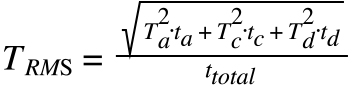
TRMS = root mean square (continuous) torque (Nm)
Ta = total torque required during acceleration (Nm)
Tc = torque required during constant velocity (Nm)
Td = torque required during deceleration (Nm)
ta = time for acceleration (s)
tc = time for constant velocity (s)
td = time for deceleration (s)
ttotal = total time for move (including any dwell time between moves) (s)
The result of the RMS torque calculation is a steady-state torque value that would produce the same amount of motor heating as all the various torques the application requires during its move profile.

Intermittent operation | peak torque
The intermittent torque zone represents the highest torque the motor is able to produce at a given speed for a limited amount of time (typically a few milliseconds), as specified by the manufacturer. For most applications, the peak, or intermittent, torque occurs during the acceleration phase of the move profile, when additional torque is required to overcome the system’s inertia.
![]()
Ta = total torque required during acceleration (Nm)
Tc = torque required during constant velocity (Nm)
Tacc = torque required due to acceleration (Nm)
![]()
Jt = total inertia of the system (kgm2)
a = angular acceleration (rad/s2)
A servo motor’s maximum torque is limited primarily by heating (due to the amount of current required to produce high torque), while its maximum speed is limited by the motor’s back EMF (voltage produced as a result of motor rotation, which opposes the supply voltage and reduces motor speed). It’s important to note that the application’s maximum torque and maximum speed must fall within the intermittent duty zone. If either value exceeds the motor’s intermittent curve, damage to the motor or drive could occur.

Leave a Reply
You must be logged in to post a comment.