With the range of linear actuators on the market, it’s becoming easier for machine builders and end users to find a standard or “customized standard” product that meets even the most unique application requirements. But there are still times when it makes sense, from a financial or technical standpoint, to design and build an actuator in-house.
However, the make vs. buy decision isn’t as clear-cut as simply adding up the costs of do-it-yourself components and comparing that to an off-the-shelf solution. Choosing between a homemade actuator and a pre-made one means considering many factors, some of which are difficult to quantify in terms of time or dollars. In addition to the technical details of design and assembly, there’s the basic business evaluation of whether it can (and should) be done in-house, and the often-overlooked factor of after-sale support.
Linear-actuator business evaluation
The first question a company should ask before they embark on making their own linear actuator is: do we have the expertise to do this in-house? Keep in mind that this includes not only the mechanical design, but also sizing and selecting the motor and controls and integrating the system. In many cases, one department or functional area has experience in mechanical design, while another department has the electrical expertise. In these cases, it’s important to capture both knowledge sets by setting up a cross-functional team for the design and engineering phase.
If the answer to the expertise question is “yes” the next thing to consider is whether you have the capacity and resources to do it in-house. This is a question that is often glossed over, because managers assume that if a project is done in-house, the company has control over quality, cost, and timeline. But making your own actuator means relying on multiple outside suppliers and being at the mercy of their delivery and quality. If the project is delayed, customers could be affected or profits could be impacted.
Key questions:
Do we have the linear motion and controls expertise to build the actuator in-house?
What are the consequences to us and to our customers if the project is delayed?
Actuators manufacturing and assembly requirements
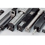
Building an actuator in-house means that you have the freedom to design it for your specific needs. The main components of any actuator are the base, the guideway, and the drive unit. One of the simplest types of actuators to build in-house is a design based on an aluminum extrusion. The benefit of using an extrusion is that they are readily available in a broad range of cross-sections and lengths. They also require little or no modification for mounting the guides and the drive mechanism. The drawback to using an extrusion is that, when high travel accuracy is required, it’s difficult to obtain a precise mounting surface.
The next option is a machined base plate. Relatively inexpensive and easy to machine, aluminum plate is a good solution for many in-house built actuators. If very high travel accuracy and rigidity are needed, machined steel plate is typically the best choice. Whether aluminum or steel, if a machined base plate is used, be sure to assess whether the machining can be done in-house. (This also applies to other machined parts, such as motor/gearbox mounts, carriage plates, and protective covers. These items can easily be overlooked when evaluating the time and capacity needed for in-house production.)

Image credit: NOOK Industries, Inc.
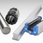
The type of guide to be used is often decided hand-in-hand with the decision regarding the actuator’s base structure. When an aluminum extrusion is used as the base, the best choice is typically a single guide based on cam rollers, wheels, or round shaft and linear ball bushings. For higher rigidity, profiled rails and carriages can be used. But unless the extrusion can be machined for a precise mounting reference, the benefit of higher travel accuracy that profiled rails normally provide will be forfeited by inaccuracies in the extrusion.
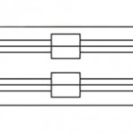
Applications that have high moment loads typically require two guides mounted in parallel, which necessitates the use of either a very wide extrusion, or a base plate to accommodate the side-by-side guides. The drive mechanism, regardless of whether belt, screw, rack & pinion, etc., should be mounted between the two guides in order to reduce the effects of binding. In dual-guide designs, it’s important to align the two guides properly to avoid binding, which can cause additional forces on the bearings and reduce their service life.
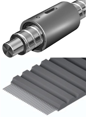
Drive mechanisms usually fall into one of two categories: belts or screws. Belt drives are relatively easy to integrate since they don’t require precise alignment. However, they must be properly tensioned to remove “slack” from the belt and allow it meet its force rating. Tensioning during assembly is usually not an issue, but think about how the end-user will check the belt tension and re-tension it if necessary. This should be a relatively simple maintenance process and not require significant disassembly and reassembly time for the user.
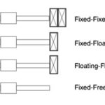
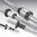
If a ball or lead screw is used as the drive mechanism, you’ll need to determine what type of end support is needed. The fixed-simple arrangement (an angular contact thrust bearing on the driven end and a single ball bearing on the non-driven end) is the most common, but if significantly high speeds or buckling loads will occur, a fixed-fixed bearing arrangement might be more appropriate.
Key questions:
Can the necessary machining, alignment, and assembly be done in-house?
Does manufacturing have the capacity to meet the required production?
Customer-support needs for actuator end user
Most actuators perform a critical function in the machine or process, and downtime can be catastrophic to production output. This makes customer support an essential consideration in the make vs. buy decision. Do you have staff who can support the actuator if troubleshooting or service are needed? Are you able to carry the spare parts required for quick repairs? These considerations are important whether the actuator is part of a production machine sold to external customers, or part of an in-house machine, where the customer is one of your own manufacturing or production departments.
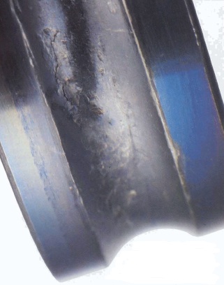
Also remember that components with rolling or recirculating elements will likely need re-lubricating during the life of the machine. This is especially true for ball screws, linear ball bearing guides, and profiled rail guides. Even if components are designated as “lubed for life,” the application conditions may warrant re-lubrication during the machine’s useful lifespan. Taking user-facilitated maintenance into account during the design phase will help ease service requirements.
Key questions:
Do we have the structure and resources (staff and inventory) to support end users if troubleshooting and repairs are needed?
How easy is it for the user to perform basic maintenance?
Just as buying a pre-made actuator should include an assessment of all the costs involved, making an actuator in-house requires considering the engineering, manufacturing and service requirements, as well as the cost of components.



Leave a Reply
You must be logged in to post a comment.