
Applying an electric motor is easier when one knows what it will output for a given input. The simpler it is to predict that, the more elegant and robust the design. To this end, some linear motors have linear force-current relationships so engineers don’t need to accommodate nonlinear effects through approximation or additional terms in F(I) equations. This in turn boosts accuracy and repeatability, as output force is the force requested every time.
By Brian Scott, Ph.D. | Nippon Pulse America
Consider the world of machine tooling for parts production. Here, machine-movement accuracy and precision are paramount to get tolerances and surface finishes required today. Final part dimensioning, surface finishing, and mill cutters sharpening is often only possible through grinding operations. But grinding is a particularly demanding operation that generates significant vibration, heat, and abrasive particles but must maintain positioning and speed accuracy. Here, the axis-translation mechanisms dictate maximum accuracy possible, as well as the long-term cost of machine ownership.
Machine designs must move axes to set positions and track that position relative to the workpiece. Maintaining movement of workpieces or tooling requires solid design of three machine features: the mechanical components; the command and control of the movement (through control boards and servo loops); and the translation mechanism (whether that takes the form of linear motor or rotary motor driving a ball screw). Let’s consider one permutation — force generated by linear electric motors.
Newton’s first law tells us that to alter an object’s motion, a force must act on it (F=ma). So in a machine-tool application, we must apply a force of enough magnitude to overcome the object’s mass as well as resistive forces to put it on the necessary path for shaping, honing, or grinding to specification. Applied force vectors must maintain accuracy and precision so they output the right motion every stroke. But this is only to get our workpiece into the target position during a set time, and doesn’t account for the effects of work hardening, elastic and inelastic deformation, tool deflection, and other production factors.
Within a linear electric motor, motion arises from the interaction between an electromagnetic field created by current-carrying coils and permanent magnets. Creating motion necessitates generation of force, and electric motors output force when a current supply creates a magnetic field within them. When opposite polarity fields of the electric and permanent magnets align, the motor is stationary. When the electromagnetic fields are offset, it generates a force and movement occurs. Force generated is directly related to the current magnitude in the coils, as current determines the magnetic field size … and this determines output force.
That’s why the magnitude, timing, and direction of the current is one of the more important control inputs for creating any given motion profile with electric motors.
The relationship between current and motor performance lays the foundation for how a motor executes motion commands. If a 20-N force must move to position (X, Y) the controls must know how much current to supply. Ideally the force (F)-current (I) relationship (F (I)) is linear so that a small change in current prompts a similarly small change in force over the entire operation range. But it’s more complicated when the relationship is nonlinear or has a nonlinear regime that takes large changes in current to get smaller changes in force.
Motors with nonlinear regimes necessitate advanced servo loop systems to accommodate changing force outputs for current.
Why some motors have nonlinear F(I) relationships
Some motors have a nonlinear F(I) relationships because the changing electromagnetic fields that create and control motor motion induce current flow in magnetically susceptible conductive materials. They are called eddy currents and arise just as current flow in conductors creates magnetic fields. In short, electromagnetic coils in some motor types induce eddy currents in adjacent motor parts. These eddy currents then create an additional magnetic field. Because magnetic fields are a vector quantity, the direction and magnitude of all the interacting fields are important, as they sum up over space … affecting the overall force generated by reducing the field strength between the primary magnetic components.
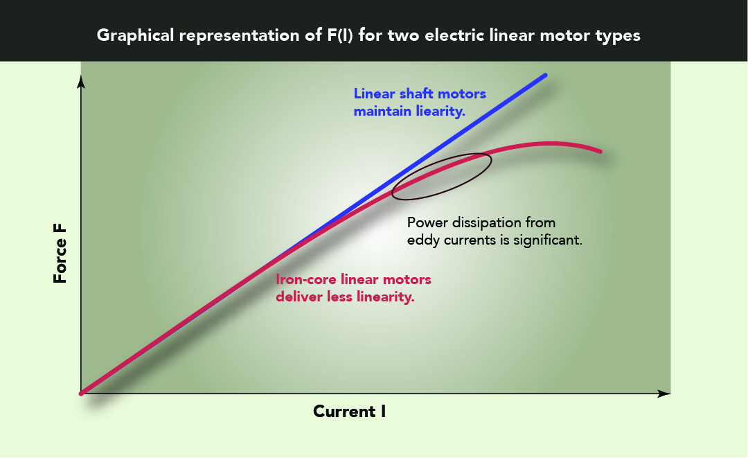
What’s more, as controls increase current to generate more motor force, eddy currents and their magnetic fields grow. This effect produces a nonlinear F(I) relationship in iron-core-type linear motors. When any large amount of a conductive material moves in relation to magnetic fields, eddy currents result. The presence of necessary heat sinks on ironless linear motors also creates nonlinear affects in F(I) because eddy currents also arise from interactions between the magnetic fields and heat sink. Some design features aim to reduce (but can’t eliminate) eddy currents in these situations.
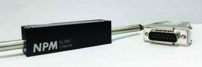
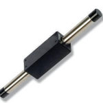
Some linear-shaft motors have a linear force-current relationship
The basic structure of linear shaft motors from some manufacturers eliminates the generation of eddy currents that cause the F(I) relationship to be nonlinear.
Here’s some background on how magnetic fields create large or small eddy currents to explain why these motors avoid the problem on nonlinearity.
Each material type has set level of susceptibility to magnetic-field-created eddy currents. For magnetic fields with low frequency of change, the main materials differentiator is conductivity. When the frequency of the fields increases, the magnetic permeability of the material also comes into play. This is reflected in the depth of penetration of the magnetic field into the material called skin depth.
When a magnetic field creates an eddy current within a metal, that consumes energy through resistive heating of the metal and by the eddy-current magnetic fields’ effect on the primary magnetic field. Power dissipation of the eddy currents per unit volume is:
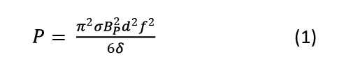
Where σ is the material conductivity, Bp is the peak magnetic field, d is the thickness of the material or laminations, f is the frequency of the field switching, and δ is the material density. So reducing material thickness and conductivity while increasing material density decreases power consumption for a given magnetic field strength and frequency.
If the frequency of the field is high enough, the magnetic permeability of the material becomes relevant, as the change in the field direction is fast enough to prevent the magnetic field from penetrating all the way through the material before switching directions. This creates a skin effect, in which the magnetic field only partially penetrates the metal. The depth of penetration is a new effective depth in calculating power dissipation. Skin depth is:
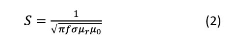
With μr being the relative magnetic permeability of the material and μ0 the permeability of a vacuum. As μr and σ increase skin depth decreases, which is why high-conductivity and high-permeability materials are suitable around magnetic fields.
Reconsider power dissipation. A relevant component here on the force-versus-current relationship is the magnetic field in equation 1. As the magnetic field increases, power dissipation increases as the second power of the field intensity magnitude. The coil-generated magnetic field that generates the eddy current is:
Where n is the turn density of the coil and I is the current. This equation shows magnetic-field intensity is linearly related to current. In iron-core motors, μr is the relative permeability of the iron composition in the core. For those motors, the core is present to create a larger magnetic field than that of an air-core coil (as the design uses half the permanent magnets’ magnetic flux).
Next, consider force generated by coil interacting with a permanent magnetic field. Force between the magnetic field generated by the coil and permanent magnet is (in a general sense):
For permanent-magnet motors the magnets are laid out so that only one pole interacts with the magnetic field of a coil at any given time. It’s this relationship that creates the linear force. If both poles interacted, rotational torque would be created. The force equation shows that the force-current relationship is linear for a given angle orientation between the field direction of the coil and field direction of the permanent magnet. When the field lines cut each other at 90° it generates maximum force.
Linear-shaft motors from some manufacturers have a linear F(I) relationship because the motors don’t have a significant amount of conductive material surrounding or adjacent to the electromagnetic coils. For other motors that have this material, there’s a counteracting magnetic field and power dissipation through resistive heating (I2R). We can see this in a qualitative sense by contemplating equations 1, 3, and 4.
Current and the created magnetic field in the coils is linear (as is the current-force relationship) but the power dissipation of the eddy currents is not. When a design has enough material to interact with the motor’s magnetic field, power dissipation becomes important at higher currents (magnetic field strengths) due to the nonlinear power dissipation relationship. For an electric motor, power into the motor is current time voltage (P=IV) and power dissipated is usually due to the resistive heating loss or I2R. Consider eddy currents: Energy goes to generating current and magnetic fields in the conductive material. This energy isn’t used to generate force between the coils and permanent magnets.
This non-useful power dissipation grows as the square of the magnetic field and has greater negative impact on the production of force at higher currents. This is the origin of the nonlinear relationship seen in iron-core and core-less with heat sinks at higher force outputs. Complicating matters is that there’s an insignificant amount of conductive material surrounding and in the magnetic coils (iron-core motors) or external heat sinks (core-less motors) to keep the motor cool enough to operate.
One linear shaft motor avoids this problem. It has a permanent-magnet shaft with a high-intensity magnetic field and a small spatial distribution at each pole. The symmetry of its electromagnetic coils about its shaft (and field properties of the permanent magnets) generate significant force without necessitating an iron core to boost the coil-generated magnetic field. This linear shaft motor’s operating temperature is 135°C without loss of force or motor stiffness due to the motor design. That’s in sharp contrast to core-less motors in which heat can cause separation or movement of the permanent magnets from fixed locations.


Leave a Reply
You must be logged in to post a comment.