
From a mechanical standpoint, one of the more challenging applications in linear motion has traditionally been to move two or more loads independently, as is required in some handling, transport, and inspection applications. While using multiple linear systems, or preassembled actuators, is a simple solution mechanically, this option typically requires a significant amount of space and cost. But there are several types of linear systems that allow users to mount more than one load and move each one independently.
One of the most common linear motion systems for moving multiple loads independently is the linear motor. Most linear motor designs — whether iron core or ironless — use forcers that contain windings and are powered directly, so multiple forcers can be installed on the magnet track and controlled with different move profiles and strokes. Linear motors with multiple forcers, or carriages, are often used for highly dynamic moves that require very precise control over velocity or position. In fact, many linear-motor-based conveyor systems are based on the concept of a linear motor with multiple forcers.
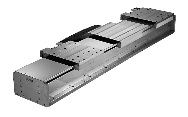
Image credit: Hiwin
Another traditional linear motion system that allows multiple loads to move independently, is the rack and pinion drive. Because the motor and gearbox are mounted directly to the pinion, it’s relatively simple to mount additional motor-pinion combinations on a single rack, with each programmed for a specific travel and move profile. Rack and pinion systems with multiple, independent carriages are ideal for large gantry and transport applications and are often used in robot transfer units.
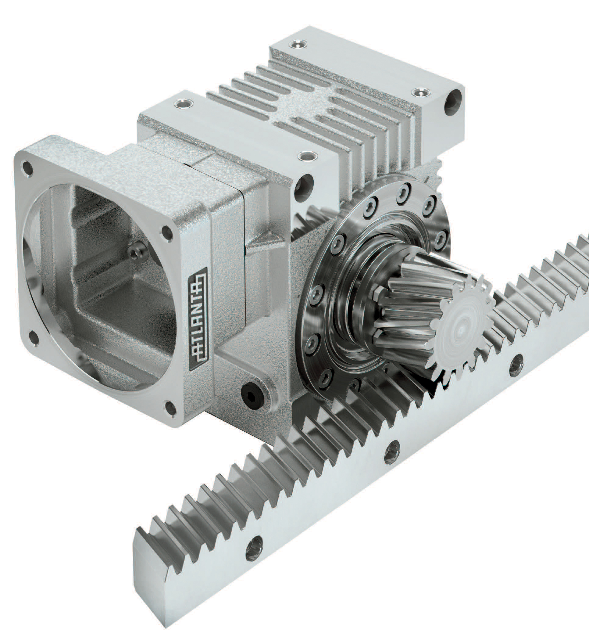
Image credit: Atlanta Drive Systems

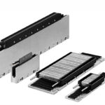
Image credit: Bell-Everman
A less traditional solution for moving multiple loads independently is to use a belt drive actuator — but not with the typical belt-and-pulley arrangement that many of us are familiar with. This type of linear actuator uses two belts that are configured in a specific way, similar to a rack and pinion drive.
One belt is static and mechanically fixed to a base, such as an extrusion — analogous to the rack in a rack and pinion drive. The other belt is a short, continuous loop that snakes over a motor-driven pinion and through idler rollers on each side of the pinion. The load is attached to a carriage, which contains this moving motor-pinion combination. Like the rack and pinion system, the dual-belt actuator design makes it simple to add more carriages — each with its own motor-pinion assembly — and control them independently. The dual-belt design also puts tension on the belt where it comes into contact with the pinion, which eliminates backlash and minimizes belt stretch.
This video from Bell-Everman shows their dual-belt actuator design, which allows multiple carriages to move independently on a single actuator.
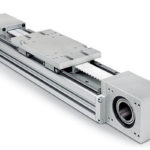
There are also actuator designs that use two ball or lead screws — one with a left-hand thread and one with a right-hand tread — that are pinned or welded together. Each screw has a nut and carriage, and one motor drives the entire assembly. This setup allows the carriages to move simultaneously, but in opposite directions — moving either toward or away from each other with the same move profile. This is a less flexible arrangement than the linear motor, rack and pinion, or dual-belt designs described above, but it can be useful in applications that require a clamping-type motion with precise force and speed control.
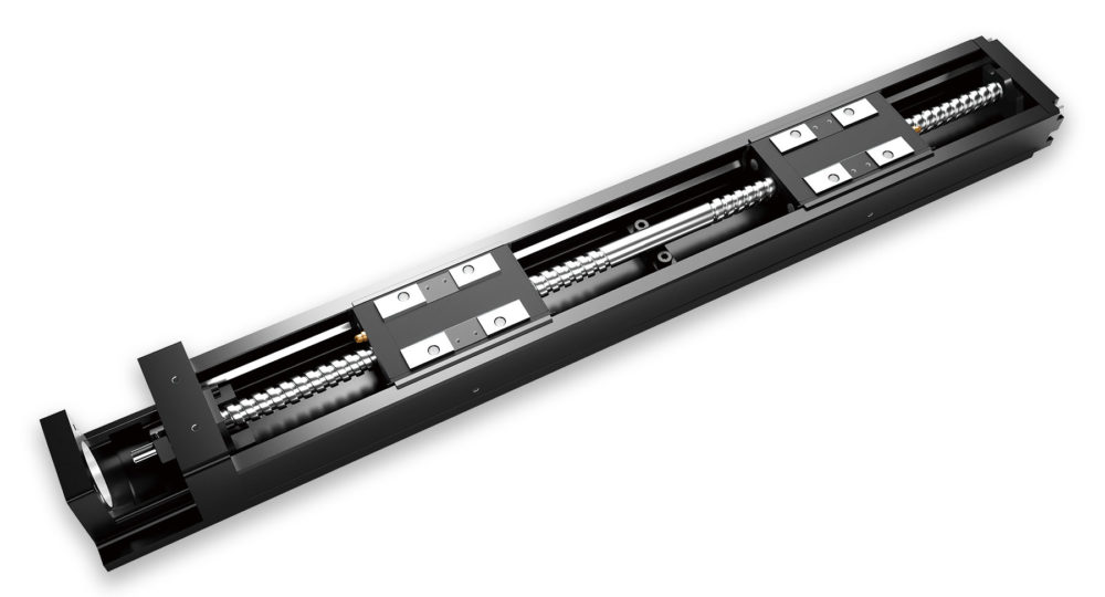
Image credit: THK


Leave a Reply
You must be logged in to post a comment.