
Updated August 2017 || Linear actuators come in myriad configurations to suit almost any application, environment or industry. They’re primarily categorized by their drive mechanism; then manufacturers use other features such as the type of guide and housing to further differentiate them. Below is an explanation of the most common linear actuator categories.
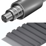
Belt-driven and screw-driven actuators
Although belt and screw drives are different technologies, it makes sense to put them in the same category because they are the two most common types of electromechanical actuators. Most manufacturers of linear actuators offer both belt and screw-driven options.
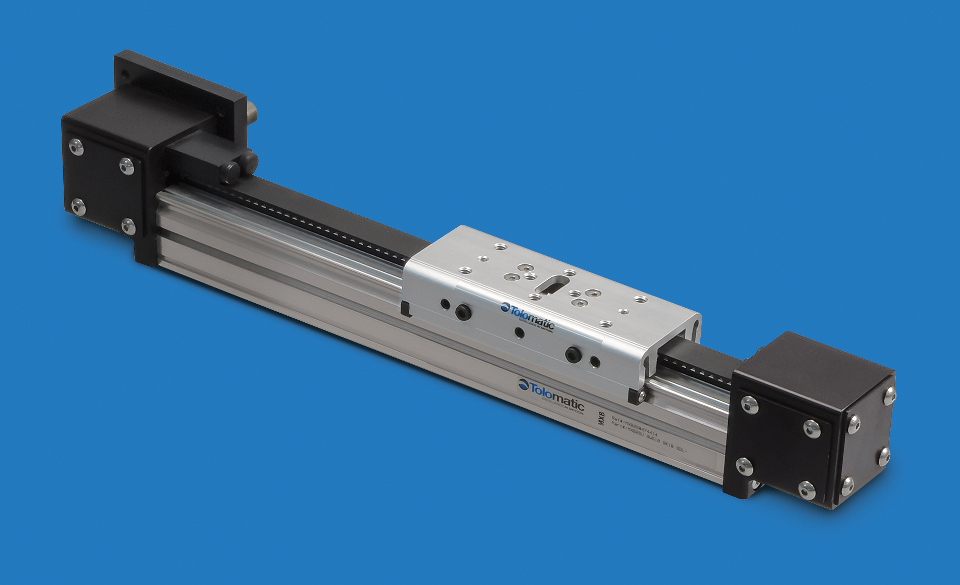
Belt driven actuators can use a variety of guide mechanisms, with plain bearings, cam-roller guides, and recirculating bearings (riding on a profiled rail or round shaft) being the most common. Because their strengths are high speeds and long strokes, belt-driven systems are often housed in an aluminum extrusion or in an open configuration with no protective housing.
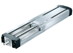
Image credit: Bosch Rexroth Corp.
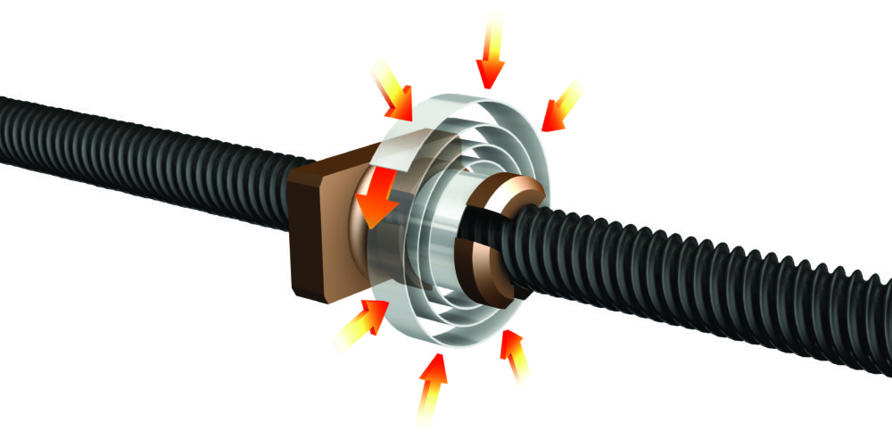
Within the screw driven category, there are two sub-categories — ball screw driven and lead screw driven. While ball screw actuators have higher repeatability and thrust forces than lead screw actuators, both provide inherent gearing through the lead (pitch) of the screw.
The most common guide system for screw driven actuators is the profiled rail, although lead screw types are sometimes guided by plain bearings. Because screw driven actuators require end bearings that must be rigidly mounted, they are often enclosed in an aluminum extrusion. However, when high travel accuracy is required, ball screw types are commonly offered with a machined steel housing.
One design that you won’t find is a ball screw actuator with cam rollers as the guide mechanism. This is because the strength of cam roller guides is high speed, whereas ball screw actuators are primarily used for high repeatability and high thrust force, with limited speed capabilities. Using cam roller guides in a ball screw driven actuator would be comparable to putting racing slicks on a Hummer. It can be done, but it wouldn’t make much sense.
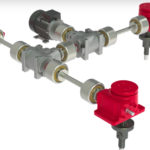
Pneumatically driven actuators
Although they’re not electromechanical devices like the other actuator types, their prevalence in automated equipment makes pneumatic driven versions an important category of linear actuators. Pneumatic actuators can be further divided into two sub-categories: slider-type and rod-type.
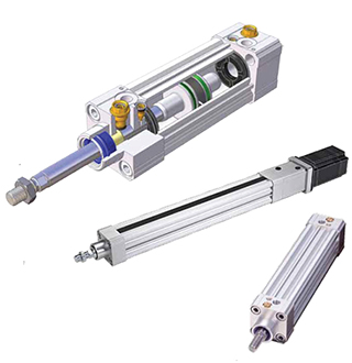
In slider-type actuators, the motion is contained within the limits of a housing and the load is mounted to a slider (also referred to as a carriage, saddle, or table).
In rod-type actuators, the motion is produced by a rod that extends and retracts from a housing. The load may be mounted to the end of the rod, or the rod can be used to push the load. (Think of pressing or stamping a label onto a carton, or pushing defective products to a diverter lane along a conveyor.)
Slider-type pneumatic actuators can be guided by recirculating or plain bearings, depending on the load they’re designed for.
Rod-style versions are not typically designed for radial (downward/upward/side) loads, and use simple plain bearings to provide guidance to the rod, without significantly contributing to load-carrying capacity.
Note: Ball screw driven actuators are also offered in both slider- and rod-types, making the actuator family tree even more complex.
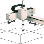
Rack-and-pinion driven actuators
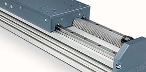
Image credit: Rollon
For extremely long lengths and robustness against contamination, rack and pinion drives are often the best choice. However, these characteristics make finding a suitable guide system difficult in some applications.
For extremely long lengths, joined profiled rails are sometimes used, but when contamination is a significant concern, metal wheels are usually preferred. A unique feature of rack and pinion types is their ability to drive multiple carriages independently. A common application for rack and pinion actuators is the overhead gantry, often found in automotive production.
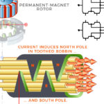
Linear motor driven actuators
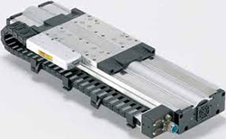
Image credit: Parker Hannifin Corp.
Linear motor actuators are also capable of long travel lengths with multiple carriages, but they’re primarily used for high-precision, highly dynamic motion.
To complement the strengths of the linear motor, these actuators use high precision profiled rails, crossed roller guides, or even air bearings as their guidance system.
Linear motor types can be mounted in an extruded housing or on a machined aluminum plate, but in order to meet the highest travel accuracy specifications, they can also be mounted on a machined steel plate or granite base.
While there are very few “standards” in the linear actuator industry, one thing that manufacturers have done a good job of adhering to is the distinction between actuators and stages. When the mounting surface is a machined steel or granite base, the term “stage” is used. The performance difference between stages and actuators has primarily to do with travel accuracy. Stages hold much higher travel accuracies than actuators and use linear motors or very high precision ball screws for extremely smooth, precise positioning.
With so many options, choosing the best linear actuator is a complex task, and there’s not one “right” way to make a selection. The best place to start, however, is usually with a manufacturer’s sizing software or selection program. Still, the results often include several choices, which can be narrowed down by looking at non-quantitative criteria, such as ease of maintenance, integration with existing components or systems, and space constraints.
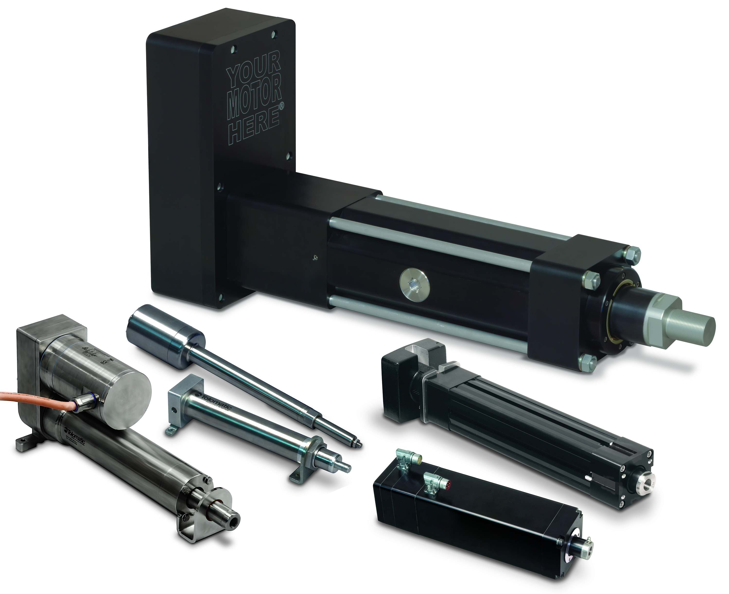
Feature image credit: Tolomatic, Inc.

Good article!