
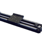
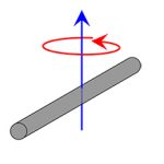
Power transmission shafts — on motors and gearboxes, for example — are subjected to torque loads that result in torsion, or twisting of the shaft about its axis. Similar to structures under tension or compression, two important mechanical properties of shafts under torque loads are shear stress and shear strain.
Stress is a material’s resistance to an applied force, and strain is the deformation that results from stress. Shear stress and shear strain (which are caused by torsional loads) occur when a force is applied parallel or tangent to an area. Normal stress and normal strain (which are caused by tension and compression) occur when a force is applied normal (perpendicular) to an area.
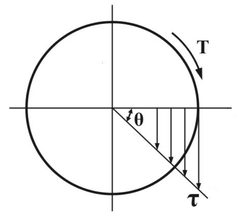
The torsion, or twist, induced when torque is applied to a shaft causes a distribution of stress over the shaft’s cross-sectional area. (Note that this is different from tensile and compressive loads, which produce a uniform stress over the object’s cross-section.)
Torque vs. Moment:
Torque is force applied at a distance that causes a change in angular momentum. A moment is also a force applied at a distance, but it does not cause a change in angular momentum. In other words, torque causes a body to rotate about an axis, whereas a moment load does not cause rotation.
Shear stress depends on the applied torque, the distance along the radius of the shaft, and the polar moment of inertia. (Note that polar moment of inertia is a function of geometry and does not depend on the shaft material.)
![]()
τ = shear stress (N/m2, Pa)
T = applied torque (Nm)
r = distance along radius of shaft (m)
J = polar moment of inertia (m4)
When shear stress is being measured at the outer edge of the shaft, the letter “c” is sometimes used in place of “r” to indicate that the radius is at its maximum.
The polar moment of inertia (aka second polar moment of area) for a solid cylinder is given as:
![]()
The amount of shear strain is determined by the angle of twist, the distance along the radius of the shaft, and the length of the shaft. The equation for shear strain is valid in both the elastic and plastic ranges of the material. It’s important to note that shear strain and shaft length are inversely proportional: the longer the shaft, the lower the shear strain.
![]()
γ = shear strain (radians)
r = distance along radius of shaft (m)
θ = angle of twist (radians)
L = length of shaft (m)
Also note that at the center of the shaft (r = 0), there is no shear strain (γ = 0). Conversely, shear strain is at its maximum value (γ = γmax) at the outer surface of the shaft (r = rmax).
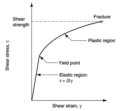
Similar to the modulus of elasticity (E) for a body under tension, a shaft in torsion has a property known as the shear modulus (also referred to as the modulus of elasticity in shear, or the modulus of rigidity). The shear modulus (G) is the ratio of shear stress to shear strain. Like the modulus of elasticity, the shear modulus is governed by Hooke’s Law: the relationship between shear stress and shear strain is proportional up to the proportional limit of the material.
![]()
OR![]()
G = shear modulus (Pa)
Note that the process of yielding for a shaft in torsion is not as straightforward as the process of yielding for a structure in tension. This is because bodies subjected to tension experience a constant stress across their entire cross-section. Therefore, yielding occurs simultaneously across the entire body.
As described above, for a shaft in torsion, the shear stress varies from zero at the center of the shaft (the axis) to a maximum at the surface of the shaft. When the surface reaches the elastic limit and begins to yield, the interior will still exhibit elastic behavior for some additional amount of torque. At some point, the applied torque causes the shaft to enter its plastic region, where the strain increases while torque is constant. Only when the torque causes fully plastic behavior does the entire cross-section yield.
Feature image credit: R+W America


Leave a Reply
You must be logged in to post a comment.