Updated November 2018 || By Lisa Eitel • Brakes, clutches and torque limiters serve similar functions in packaging machinery, medical equipment, industrial hoists and installations. Essentially, brakes stop and hold loads while clutches and torque limiters disengage and engage power-transmission outputs to transfer torque from an input. Torque limiters usually modulate power transmission to protect mechanical equipment from overload.
Job-specific variations abound. For example, some brake and clutch versions engage directly with linear rails.

When selecting brakes, clutches and torque limiters for a given application, engineers must pick between mechanical, electric, fluidic or self-actuation. Electric brakes are easy to control and cycle, even to a couple thousand cycles per minute. In contrast, common air-actuated brakes and clutches run coolly and maintain hold with minimal power. Friction brakes with disc, drum and cone morphologies work well as emergency brakes because of their failsafe holding—essential on conveyors, escalators, airport-baggage handlers, elevators and other safety-critical designs.
The size and type of brake most suitable for a given design depend on whether the machine needs emergency stops or softer stops that sacrifice brakes to protect loads from shock. Then, other application criteria (including the machine envelope, thermal capacity, cycle rates, and inspection and repair schedules) dictate the final selection. In other machines, it’s more important that brakes prevent shifting loads and misalignment.

In most cases, it’s best to size brakes and clutches to the motor torque of the machine axis. But especially for axes where the brake must stop a vertical load, engineers should account for the fact that motors can temporarily draw added current to output more than their rated torque. Helpful resources include published performance curves from brake and clutch manufacturers. These list dynamic torque ratings for various operating speeds to help engineers match brakes and clutches to peak motor-output torque.
Beyond these general guidelines, fast, hot and other extreme applications require extra evaluation. Some tips:
Spring-set brakes benefit motion designs that slow loads with the motor before the brake engages; they’re also suitable as holding mechanisms.
Machinery that runs beyond a few hundred cycles per minute may require brakes and clutches that are larger than performance curves indicate.
Industrial designs that operate in hot environments may benefit from friction brakes with specialty friction-surface geometries and materials (such as phenolic resin or ceramic). Motion applications that don’t get a lot of maintenance also benefit from the longer life these friction materials get.
Brakes that use permanent magnets for operation automatically adjust for wear, so they excel in industrial machines subject to slow but steady on-and-off cycling.
One brake example: Safety for linear motion
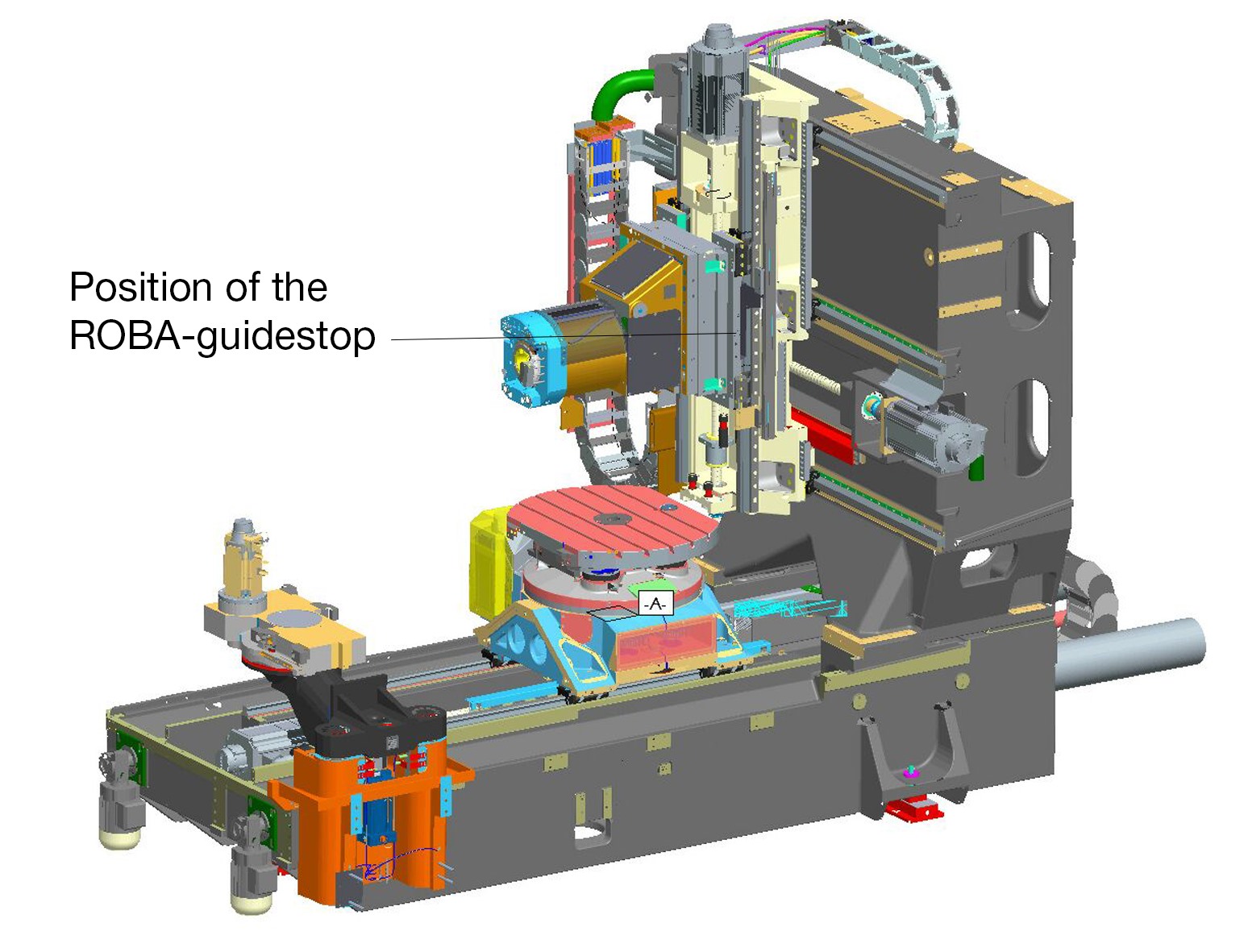
In machine tools and machining centers, rail brakes can boost safety while improving accuracy and performance. Consider how suspended loads present a hazard in machines and systems, especially if people are below. During falls or crashes, the design must stop the load as quickly as possible to protect people and the machine.
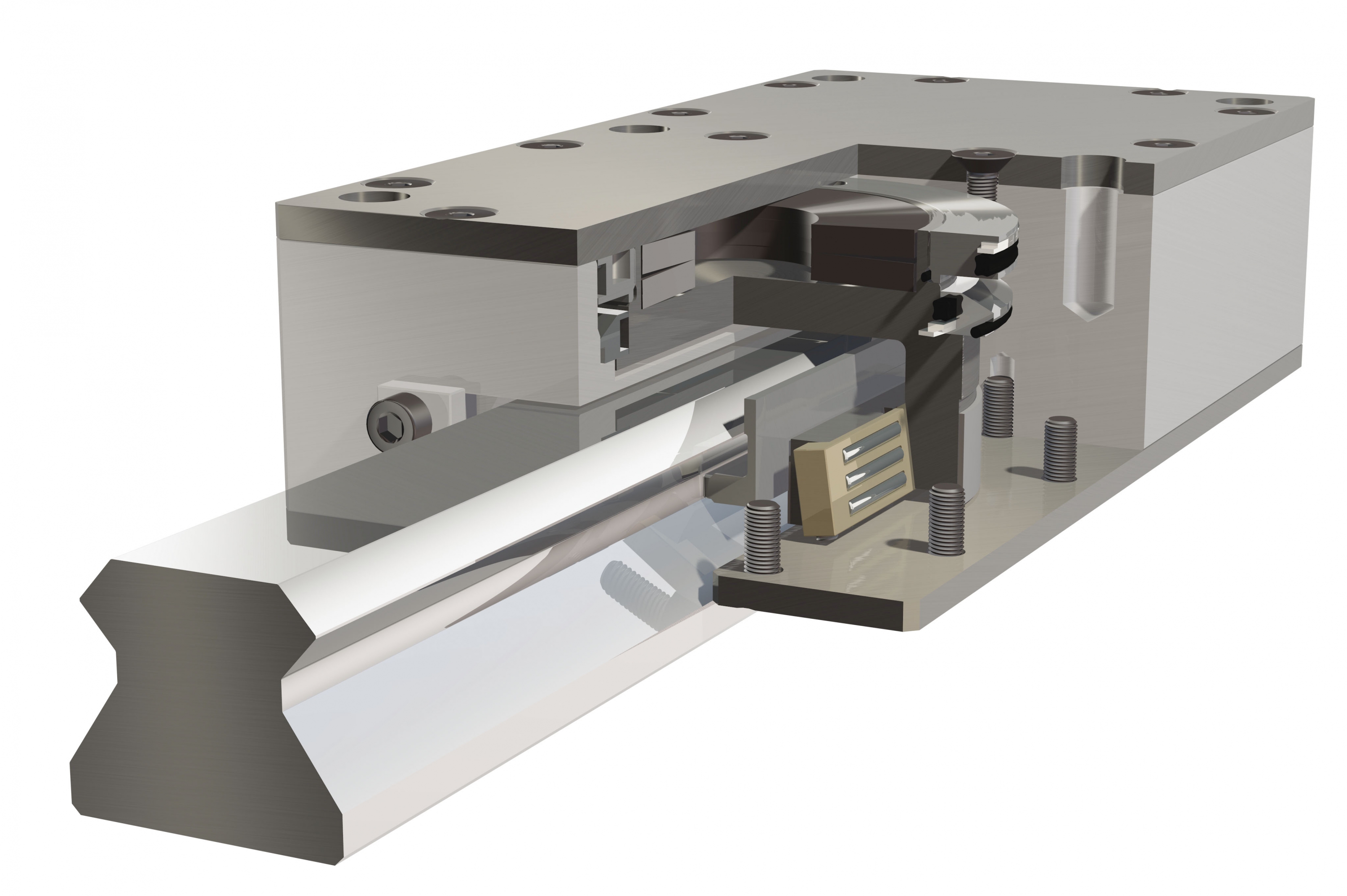
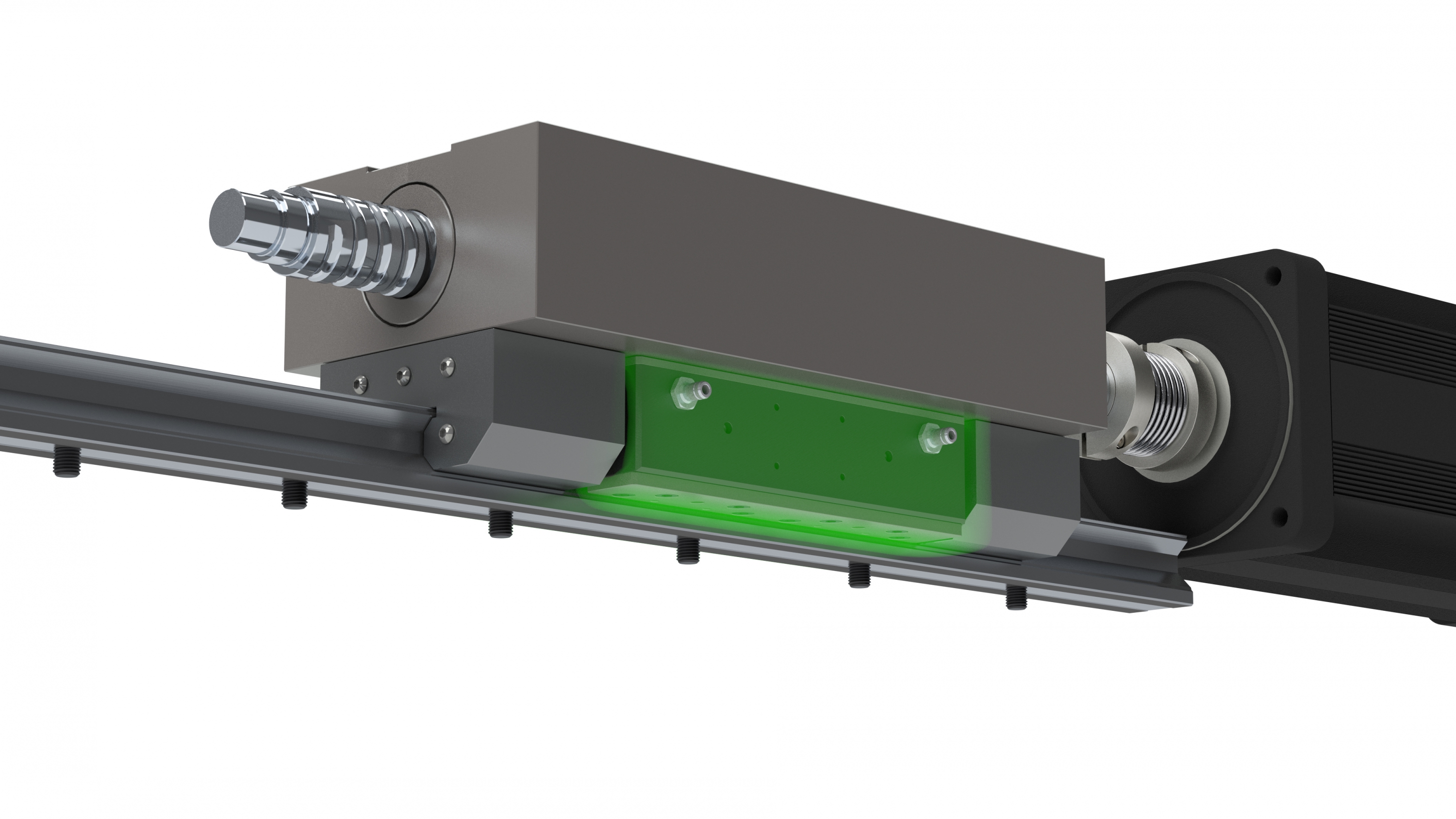
So, some safety brakes (in the form of clamping units that engage profiled rail guides) brake movements safely and quickly by rigidly clamping the axes while running. Case in point: Backlash-free ROBA-guidestop profiled rail brakes from Mayr Corp. now come in eight sizes for nominal holding forces from 5 to 34 kN. The designs are dimensioned for four rail sizes made by established linear guide manufacturers. A short constructional design and the integrated switching-condition monitoring use a contactless proximity switch.
The guidestop brakes mount directly to masses, which is especially useful for gravity-loaded axes that pose a risk to nearby workers. Drive elements between the motor and moving mass (spindles and nuts, shaft couplings or gearboxes) don’t affect overall machine safety as in motor brakes that rely on drive elements to transmit braking torque to the load. Another drawback of the motor-brake setup (not to mention pole brakes or band brakes) is that everything between the brake and carriage degrades rigidity. ROBA-guidestop safety brakes avoid this issue.
The ROBA-guidestop safety brakes work as fail-safes, as they close when de-energized. Tensioned cup springs press brake shoes onto the profiled rail’s middle (to clamp it). Then hydraulics release the ROBA-guidestop with nominal pressure of 70 bar—low compared to the holding force. The brake mechanism is for relatively long stroke paths, so compensates for profiled rails’ manufacturing tolerances without losing braking force. Two brake circuits work independently to either double holding forces or provide redundancy.

The backlash-free clamping of guidestops directly onto profiled rails also boosts the rigidity of the NC axis (for more accuracy) and minimizes vibrations (for better workpiece surface quality). What’s more, when the axis is at a standstill during machining, the ROBA-guidestop brake takes over the load, so the drive motor switches off and disconnects from the controls. This eliminates the control movements and relieves the ballscrew spindle; the closed brake absorbs axial forces.


Leave a Reply
You must be logged in to post a comment.