Comparing rack and pinion drives with other linear drives such as belts and ball screws shows that sometimes simplicity can be the ultimate sophistication.
YYC North America
These days engineers have quite a few options for actuation in a linear motion system. From various screw drives to linear motors to hydraulic systems, each comes with unique pros and cons, with some fitting better in some applications than others. The result is that there may not be a “perfect” linear motion actuator to fit every application requirement. However, there is one kind of linear actuator that may come close to a perfect ideal; the tried and true rack and pinion drive. Here we discuss the modern quest for the perfect linear motion solution and how rack and pinion systems fit a lot, if not most, of the criteria. Although some may think of rack and pinion technology as “old and clunky,” we’ll show how this isn’t true of modern day rack and pinion systems, providing a new appreciation for an old technology that – when properly selected and applied – can achieve the dynamic moves and positioning accuracies of the latest technologies, such as advanced ball screw drives and linear motors.
Re-evaluating the linear motion status quo
When a linear motion system requires high accuracy, high thrust forces, or high dynamics – or any combination of these – designers typically turn to one of three drive options: belt and pulley, ball screw, or rack and pinion. The general thinking regarding these technologies is usually something along the lines of:
- Belts are great for high speeds, but have limited thrust force capabilities and lower stiffness.
- Ball screws are great for high thrust forces and positioning accuracy, but travel and speed
are limited. - Rack and pinion systems are great for high dynamics, high thrust forces, and high positioning accuracy, but they’re old and clunky.
One of the reasons that machine builders choose rack and pinion drives is for their ability to provide extremely long stroke lengths. In fact, rack and pinions are often the drive option of choice for applications that require long travel, where properly tensioning a toothed belt drive becomes difficult. And for ball screw drives, the critical speed of the screw – the speed at which the screw begins to whip as it rotates – is directly proportional to the screw’s diameter and inversely proportional to the square of its unsupported length. So for long travel lengths with even modest speeds, the screw diameter needs to be relatively large in order to prevent ball screw whip. Rack and pinion drives, on the other hand, can be made in virtually unlimited lengths by mounting sections of rack end-to-end, without requiring an increase in the module (size) of the rack or a larger pinion.
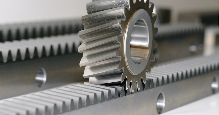
What’s more, for both belt and ball screw drives, as the stroke length increases, so does the inertia that the load must control. At long stroke lengths, this inertia can be significant. For belt drives, this is because the belt is essentially circular, so its length (and, therefore its mass and inertia) increases by a factor of approximately two as the stroke length increases. And for ball screws, longer stroke lengths typically mean both the length and the diameter of the screw will increase – resulting in a significant increase in mass and inertia. And the higher the inertia of the moved load, the more difficult it is to achieve dynamic moves – especially those that require high thrust forces at high accelerations.
On the other hand, one of the main strengths of rack and pinion systems is that their moved inertia doesn’t increase with length, so they can achieve high speeds and highly dynamic moves, regardless of the travel length.
Case study: Rack and pinion vs. ball screw for long length and high accuracy
Although ball screws are often perceived as the most accurate of the three drive mechanisms, rack and pinion systems can provide accuracy and repeatability that approaches or even exceeds that of most typical ball screw applications. As specified by DIN/ISO and AGMA quality standards, racks with helical teeth can have tooth pitch errors in the single-micron range and cumulative pitch errors of less than 25 microns per meter. And preloading a rack and pinion system can eliminate backlash, for excellent repeatability, especially when the application requires directional changes.
One of the key things to look for when selecting a rack and pinion is the manufacturer’s ability to produce higher quality racks in longer lengths. In many cases, quality class and length go hand-in-hand, with higher quality racks only available in short lengths.
But consider the case of an application that requires multiple sections of rack to achieve a long travel length. Here, the cumulative pitch error of each rack section becomes very important, as it determines the error that will be seen over the total length of the multi-part rack.
The best way to minimize the total pitch error over the full length of the rack is to use longer sections of rack with a better quality level – something that very few manufacturers can offer. For example, a rack with DIN/ISO quality class 5 (cumulative error of 0.025 mm/m) might only be available in 500 mm lengths. So for a 3,000 mm total length, six sections of rack will be required, and the total error will be 0.150 mm. However, if a manufacturer can produce racks of DIN/ISO quality class 5 in 1,000 mm lengths, only three rack sections will be required, for a total error of 0.075 mm.
Now compare this to a class T5/P5 ball screw at 3,000 mm long, which, according to DIN/ISO standards, can have a lead fluctuation (v300p) of 0.023 mm per 300 mm. This means that for a 3,000 mm long screw, the lead deviation can be 0.230 mm – more than three times the cumulative pitch error of our three-part, Q5 accuracy rack at 3,000 mm long.
Precise, dynamic motion requires control
Whether over an extended length at constant velocity, or for short, highly dynamic moves, the drive mechanism must be able to produce sufficient force to move the load with precision and control. Although belt drives can achieve long travel lengths, if the application requires a high thrust force, they’re out of the running. Ball screws and rack and pinion drives both rely on metal-on-metal contact (balls and raceways for ball screws and meshing gear teeth for rack and pinion drives) to produce high thrust forces for moving heavy loads in dynamic applications.
But even at similar lengths and force capabilities, rack and pinion drives have lower inertia than ball screw assemblies, giving rack and pinions an advantage, particularly in precision motion applications. This is because the motor only has to overcome the inertia of the pinion (the rack remains stationary), so the inertia of a rack and pinion system is quite low compared to that of a ball screw assembly, where the motor must control the inertia of the entire screw shaft and nut.
In fact, in many applications, a smaller motor can be used for a rack and pinion system than would be required for a ball screw system with similar performance. And lower moved inertia means the system can execute highly dynamic moves – higher acceleration and deceleration rates – with better control and less complex servo tuning.

This brings up another point regarding the motor’s ability to control the system for the best performance – particularly in terms of positioning accuracy, oscillation, and settling time. For applications that require long travel lengths but don’t require high thrust forces, belt and pulley systems are often the go-to choice. However, belt drives have low stiffness, and therefore can introduce significant compliance and vibrations into the system.
Even if the positioning accuracy of a belt drive meets the application’s requirements, this lack of stiffness can make precision control difficult. And because belts experience wear and stretch, stiffness changes (worsens) over time as well, meaning a system that is tuned for acceptable performance upon startup may need mechanical adjustments such as re-tensioning the belt and re-tuning the controls, well before the system reaches the end of its useful life.
Rack and pinion systems – with or without preload – have inherently better stiffness than belts. And unlike belt drives, the stiffness of a rack and pinion system doesn’t change over time, so performance is stable and predictable over the life of the system.
Preload can be achieved in a rack and pinion system by using either a dual- pinion or a split-pinion design. In the dual-pinion design, one pinion drives the system and the other is preloaded, with the amount of preload determined by the motor controller. In the split- pinion design, two pinion halves each mesh with opposite tooth flanks on the same rack. One pinion half is driven while the other is preloaded via an axial spring.
Modern rack and pinion drives excel in critical applications
Unlike their “down and dirty” counterparts of decades past, modern rack and pinion systems are manufactured with advanced technologies that produce high gear quality, accuracy, and strength, by way of precision hardening and grinding. This makes them suitable for the most critical automation and processing applications.
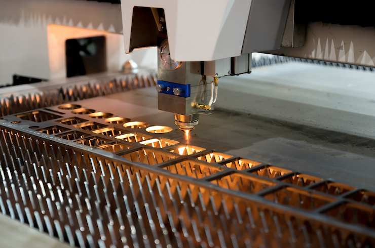
For example, rack and pinion drives are now the standard on machining centers requiring the utmost precision – whether for milling, routing, waterjet cutting, plasma cutting, or laser cutting – where they control the X and Y (horizontal) movements of tools with high accuracy and stiffness. Pick and place applications – especially in automotive manufacturing – use rack and pinions for their combination of long travel lengths, high thrust forces, and high speed capabilities. And robot transfer units – which transport articulated robots across factory and warehouse floors – use rack and pinion drives for their high stiffness and smooth motion.
YYC North America
www.yycdrives.com


Leave a Reply
You must be logged in to post a comment.