
Up until now, linear motors have been designed primarily as flat stage motors complete with cradle and guide – a format that is not necessarily suitable for every application. But a new rotationally symmetrical rotor design together with a rectangular, flange-mountable stator, enables an almost universally applicable fit.
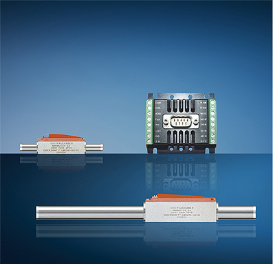
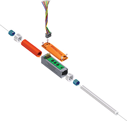
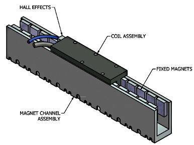
The LM 1247 motor from MicroMo is a typical example of small direct drive linear servomotors. A three-phase delta-wound coil drives the output shaft containing embedded permanent magnets, while Hall Effect sensors monitor shaft position.
The new design is largely driven by application needs, with the fact that automation and discrete applications increasingly rely on local, compact direct drives. Conventional drive concepts for translating rotational to linear motion using dc drives are available, but the smaller they become the more maintenance they tend to require.
Traditionally, there are three construction types suitable for small linear actuators: pneumatic drives, small or micromotors with spindle gears, and linear electric motors.
A pneumatic drive requires a pneumatic cylinder with a compressed air system and steel pipe (which can be gotten from a cut to length steel pipe service) or tube to operate. It involves the compression of air at an inlet port to drive a piston that in turn drives a rod. Such a setup is very simple and effective. Pneumatic linear actuators are also easy to assemble, can produce a lot of power and have very fast actuation times. On the down side, they can be difficult to adjust and not easily controllable. Pneumatic systems may not be cost effective either, as wear and mean runtime are based on a clean air system and environment. But perhaps most importantly, in a micro drive environment that needs ultra accurate positioning, this would not be a practical situation.
Micro motors with spindle gears are another linear actuation method. Here, the accuracy depends on the type of lead screw used. So the pitch and run out along with the general hysteresis of the device, including backlash, will greatly affect the precision. In general, micro motors with spindle gears are capable of producing very high precision and accurate motion, but this comes at much higher cost of using the highest quality lead screws with the best precision and accuracy.
The stator measures just 12.5 x 19.9 x 49.4 mm (W x H x L), including power connection. The rotor bar comes in two versions, each 6.3 mm in diameter and 82 or 154 mm long. This makes stroke lengths of up to 20 or 80 mm possible, which is sufficient for many microdrive applications.
The resolution or smallest possible movement of the rotor bar is just 6 µm, and repeatability (maximum deviation on multiple movements of the same kind) is 40_µm. Three linear Hall sensors combined with a motion controller limit the maximum positional error, or the difference between the set and measured position of the system, to 120_µm. As all values are determined solely electronically, mechanical tolerances, wear and tear and thermal expansion of components are of no consequence.
Linear Electric Motors
Traditional linear motors were basically a permanent-magnet rotary motor rolled out and laid flat. Imagine the stator and rotor being cut along a radial plane and then unrolled so that they could provide linear thrust. Energizing the stationary part of the motor causes motion in the moving part, which typically contains some type of conductive material.
The new linear electric motor design goes back to rotary ideas. The motor itself is contained within a nonmagnetic steel housing. A self-supporting coil sits inside, along with the sleeve bearing of the forcer rod made out of special slide-bearing material. The coils are glued and connected together and after the insertion in the housing a plastic injection makes for a self-supporting structure so that there is no core for the structure rigidity. Inside the forcer rod-a high-precision sliding cylinder-are small ultrastrong permanent magnets in the shape of a disk. The rod-magnet assembly is free to move inside and out of the coil. As the coil is energized and de-energized, this produces a magnetic field which can move the forcer rod forward or backward, creating motion. A circuit board with electronics for the three Hall sensors that determine positioning is hidden under the top cover, along with the power connection.
Traditional linear motors are essentially a permanent-magnet rotary motor rolled out and laid flat. Energizing the coil assembly produces motion.
This new design provides for almost floatational movement of the forcer rod in the sleeve bearing. Because the magnetic field is so close to the bearings, the rotor and stator operation is like a magnetic levitation train where the forcer rod “floats” in the magnetic field. This reduces the friction by orders of magnitude over traditional linear motors. Wear is limited and is a direct result of rod speed and rod loading this also limits the heat generated.
This design adds all of the benefits of a pneumatic cylinder (power, fast actuation times, and quiet operation) with the added flexibility of an electromechanical motor, such as the size and being able to operate in a dual push and pull mode.
Moving the forcer rod by hand reveals no cogging force, just a smooth motion without resistance. In other types of linear motors this residual cogging force can be clearly felt. This makes for sticktion-free operation and improvers the overall efficiency of the motor.
Discuss this on the Engineering Exchange:

MicroMo
www.micromo.com
::Design World::

Leave a Reply
You must be logged in to post a comment.