
By Jörg Tertünte and Lisa Endrijaitis, Festo Marketing Concepts
The trend in conventional linear and rotational applications is moving away from robots to energy-efficient and cost-optimized systems, as manufacturers often don’t require all the functions, large sizes and degrees of freedom robots provide.
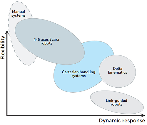
Although considered an industrial robot by DIN standards, Cartesian handling systems offer simpler and more energy efficient operations than most 4- to 6-axes, articulated arm robots. The DIN standard EN ISO 8373 states that “an industrial robot is an automatically controlled, reprogrammable, […] multipurpose manipulator, programmable in three or more axes, which may be either fixed in place or mobile for use in industrial automation applications.” However, the segmentation of such systems varies depending on the function, flexibility and dynamic response of the system.
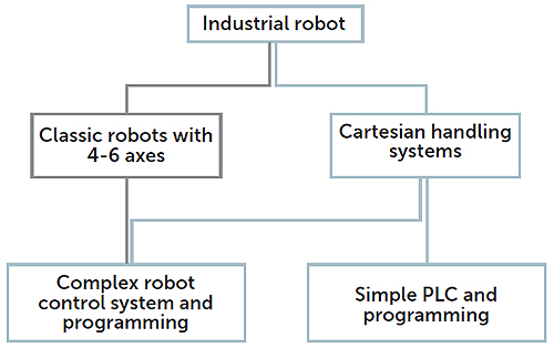
Cartesian handling systems and conventional robots with 4 to 6 axes have a relatively large overlap in terms of flexibility and dynamic response but differ when it comes to their mechanical system. Depending on the application, Cartesian handling systems are controlled either by a simple PLC (which a user may already have) for point-to-point movements or by a complex control system with robotic functions, such as for path movement. The 4- to 6-axes robots always require a complex robot control system.
Moreover, Cartesian handling systems require less space for movement and lend themselves more easily to custom and modular adaptation to application conditions. The work space can be adapted easily by changing the axis lengths.
The kinematics are thus configured to suit the requirements of the application—in contrast to conventional robots where the application peripherals must be adapted to suit the mechanical and kinematic system of the robot. The mechanical system of a Cartesian handling system is therefore part of the total solution and must be integrated into the complete system.
Customization and versatility: clear benefits
In contrast to standard solutions with 4- to 6-axes robots from the catalog, Cartesian handling systems can be customized in a modular fashion to suit the application (see Figure 3). These systems require virtually none of the compromises often found with conventional robots. With a conventional robot, parts of the application must be adapted to the requirements and capabilities of the robot. Also, the shift toward standardization and the use of mass-produced components reduces the cost of Cartesian solutions compared to conventional robots.
In addition, different drive technologies can be combined with Cartesian handling systems. The right pneumatic, servo-pneumatic and electric drives for the application are selected for each axis to achieve optimum movement in terms of efficiency, dynamic response and function.
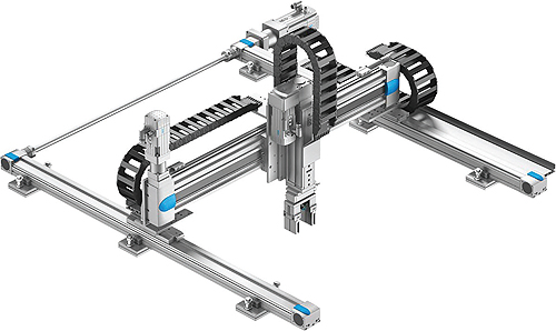
Cartesian handling systems as serial kinematics have main axes for straight-line motion and auxiliary axes for rotation. The system acts simultaneously as guide, support and drive and must be integrated into the application’s complete system regardless of the handling system structure.
Standard mounting positions
All Cartesian handling systems can be installed in any position in the space. This allows the mechanical system to be adapted ideally to the conditions of the application. Here is a look at some of the more common designs.
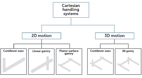
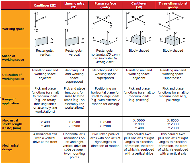
Two-dimensional – These Cartesian handling systems are divided into the categories of cantilevers and linear gantries with their movement in the vertical plane, and planar surface gantries with their movement in the horizontal plane.
A 2D cantilever consists of a horizontal axis (Y) with a vertical drive (Z) mounted on the front of it.
A linear gantry is a horizontal axis (Y) secured at both ends, left and right. A vertical axis (Z) is mounted on a slide between the two end points of the axis. Linear gantries are usually slim, with a rectangular vertical working space.
A planar surface gantry consists of two parallel axes (X) linked by an axis (Y) perpendicular to the direction of movement. Planar surface gantries can cover a significantly larger working space than robot systems with delta kinematics or SCARA with their circular/kidney-shaped working spaces.
In addition to the conventional configuration with individual axes, linear gantries and planar surface gantries also take the form of complete systems with a fixed mechanical combination with a rotating toothed-belt as the driving component. The low effective load makes them suitable for high capacities (picks/min) with corresponding dynamic response.
Three-dimensional – These Cartesian handling systems are divided into the categories of cantilevers and 3D gantries with movements on both planes.
3D cantilevers are two axes (X) mounted in parallel plus a cantilever axis (Y) perpendicular to the direction of movement, with a vertical axis (Z) mounted on the front of it.
3D gantries consist of two parallel axes (X) linked by an axis (Y) perpendicular to the direction of movement. A vertical axis (Z) is mounted on this perpendicular axis.
Note: With planar surface, linear and 3D gantries, the force is applied between the two points of support of the horizontal axes. The horizontal axis on the cantilever acts as a lever due to the load suspended on its end.
Simpler programming required
The degree of programming required depends on the function: If the system only needs to move to individual points, quick and simple PLC programming is sufficient.
If path movement is necessary, such as when applying adhesive, PLC control is no longer sufficient. In such cases, conventional robot programming is required for Cartesian handling systems too. However, the control environment for Cartesian handling systems offers a large range of possible alternatives when compared with conventional robots. Whereas conventional robots always require use of the manufacturer’s specific control system, any PLC can be used for Cartesian handling systems, in the version with the best range of functions for the application’s requirements and complexity. This means customer specifications can be adhered to and a uniform control platform can be implemented, including a uniform programming language and program structure.
With conventional robots, complex programming is often required. Consequently, a great deal of work is needed to use 4- to 6-axes systems for mechanical tasks. For example, all 6 axes always need to be moved at the same time for straight-line travel. It is also difficult and time-consuming to program “right arm to left arm” in conventional robotic applications. Cartesian handling systems offer excellent alternatives here.
Energy efficiency is high
The foundations for energy efficient handling are laid even when selecting the system. If the application requires long dwell times in certain positions, all axes on conventional robots are subject to closed-loop control and must continuously compensate for weight force.
With Cartesian handling systems, it is usually only the vertical Z axis which needs to apply force continuously. This force is required to hold the effective load in the desired position against gravitational force. This can be achieved very efficiently using pneumatic drives, as these do not consume energy in their holding phases. A further advantage of pneumatic Z axes is their low dead weight, which means that smaller sizes can be used for the mechanical components of X and Y axes and their electric motor. The reduced effective load leads to a reduction in energy consumption.
The typical strengths of electric axes come to the fore especially in the case of long paths and high cycle rates. Therefore, they are often a very efficient alternative for X and Y axes.
Conclusion
In many cases it is more efficient and economical to use Cartesian handling systems instead of conventional robot systems. For a large range of applications, it is possible to design an ideal Cartesian handling system because:
• The systems are configured for the requirements of the application in terms of optimum paths and dynamic response, and are adapted to the load.
• Their mechanical structure makes them easy to program: for example, only one axis needs to be activated for vertical movements.
• Their optimal mechanical adaptation makes them energy efficient, for example, by switching off the energy supply when at rest.
• Cartesian handling systems are space-optimized for the application.
• Standard, mass-produced components allow Cartesian handling systems to be an attractively priced alternative to conventional industrial robots.
And last, but not least: With Cartesian handling systems, the kinematics are defined by the application and its peripherals, not the other way around.
Application Examples
To further demonstrate the advantages of Cartesian handling systems, let’s take a look at some of the more common designs and their benefits in specific applications.
2D cantilever – This pick-and-place system consists of two yoke drives.
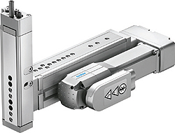
It offers:
• high mechanical rigidity and sturdy design
• pneumatic and electrical components combined
• electrical for positioning
• pneumatic for lower weight and energy efficiency
• precision in movement and positioning
• space-saving design
Linear gantry – With >90 picks/min, this linear gantry is especially suitable for highly dynamic pick-and-place applications, especially in the packaging industry.
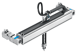
Its benefits include:
• parallel kinematic principle with two stationary motors, rotating toothed belt and low effective load
• compact and slim design
• flexible handling with free movement in the vertical plane even when installation space is limited
Planar surface gantry – This planar surface gantry can approach any position within its working space.
Key benefits include:
• 3-toothed belt axes as a planar surface gantry with rotating toothed belt for horizontal movement and positioning of the optional Z-axis
• parallel kinematic drive concept ensures low effective loads
• small version of 155 x 110 mm is frequently used in the electronics industry or in laboratory applications for positioning trays/laboratory microplates
• large version is used for tasks such as the handling of solar wafers with a maximum working space of 1800 x 2500 mm
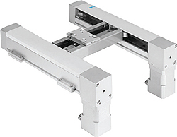
3D cantilever – Featuring a heavy-duty axis linking two guides in one mechanical system.
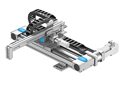
This design offers:
• maximum rigidity and load capacity of the drives due to aluminium profile that absorbs very high torques and forces
• recirculating ball bearing guide and toothed-belt or spindle drive with two parallel guides.
Three-dimensional gantry – Finally, this very compact three-dimensional gantry is designed for heavy loads, such as for X-ray examination of aluminium wheel rims. Precise examination of each rim in exactly the same position is required because tiny air pockets or foreign bodies in the cast aluminium can cause the wheels to break.
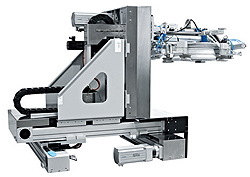
Benefits include:
• additional requirement: carefully engineered dynamic response for high process speed even in confined spaces.
• 6 axes connected in parallel ensure maximum dynamic response and rigidity
Festo AG & Co. KG
www.festo.com

Leave a Reply
You must be logged in to post a comment.