
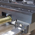
Machine frames tend to have imperfections that prevent fabricators from mounting the guides properly. Unless the frame is flat, straight, or parallel, the forces that act on the sliders inside the rails will produce uneven loads to the rollers and raceways, affecting the motion system’s operation and service life. As they wear out, pitting occurs, followed by catastrophic failure and the associated costs and downtime. Designers that choose ball-type linear bearings often devote a lot of time and expense to create rigid mounting surfaces, so the unit can align according to an application’s specific geometric tolerance.
Bearing systems account for misalignment
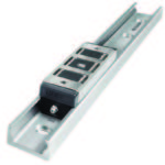
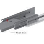
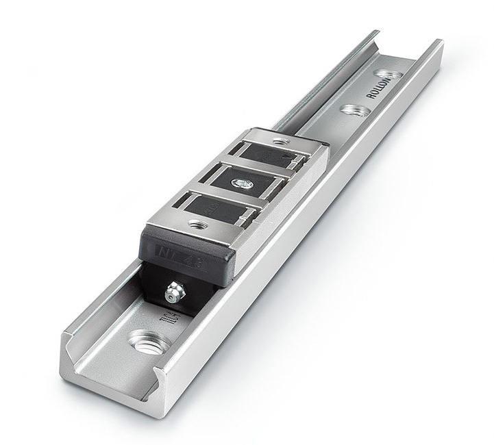 Rollon’s Compact Rail linear guide system takes a different approach: it allows for the inherent misalignment that occurs in one or two axes. For many applications, Compact Rail eliminates the need for ultra-high precision guides that require the complex and expensive framing, mounting and fabrication methods necessary to create perfect mounting surfaces. Instead, this rolling-type bearing system provides rotational and lateral freedom for its rollers within the raceways to offset misalignments in all axes. Featuring large rolling elements, rail profiles that allow them some leeway and a preload adjustment to equalize loading, Compact Rail has the flexibility to:
- Rotate up to two degrees relative to the rail without affecting the functionality or increasing wear.
- Adjust to parallelism problems in a plane.
- Accommodate localized variations caused by high spots in mounting surfaces or by an inexact assembly process.
Self-aligning bearings offer many benefits
Since self-aligning linear bearings allow for imperfections on the mounting surface, engineers have more freedom when choosing materials and assembly processes versus conventional rails. And, self-aligning bearings provide a number of cost savings, such as:
- The freedom to use lower-cost materials and fabrication methods.
- Eliminating the time and expense of grinding mounting surfaces.
- A reduced likelihood of replacing worn out rails.
Allocate design time and effort smarter
Of course, given the specifications of a particular machine, there are times when a high-precision ball-type bearing may be the appropriate choice. And machines that utilize more than one bearing may individually incorporate a ball-type rail on axes where precision is a must, and self-aligning rails for axes with less-stringent requirements. For many applications, Compact Rail not only offers design freedom, it also lets engineers accept imperfect mounting surfaces and allocate time and resources to other important tasks — all while ensuring long service life for the machine.

Leave a Reply
You must be logged in to post a comment.