
by Gwenn Gmeinder, N.A. Busines Development Manager, Sensor Products, Littelfuse
Analog and digital sensors are accurate and reliable over the long term. Here we explain how to choose them for industrial automation and motion-control applications. We define and describe the benefits of digital and analog sensors and give industrial examples. Then we apply design principles and best practices to detail a custom magnetic-sensing solution for an industrial application.
Industrial automation and motion designs, such as conveyors, elevators and pick-and-place machinery, must function within factories subject to dust and dirt. These designs often exhibit high vibration and spikes in shock force as well. Such conditions can threaten the stability of sensor circuits. Fortunately, some custom magnetic sensors sport features to ensure long-term accuracy and reliability.
Consider an application that must verify when an object such as an elevator door is closed. Here, digital versions of reed and Hall-effect sensors deliver outstanding reliability.
Basics of digital reed switches
This electrical switch requires no power to operate. A glass tube with precious metal hermetically seals its contacts.
Benefits: Reed switches are reliable for millions of operating cycles because they are immune to moisture and other environmental conditions.
Applications: Reed switches are common in microprocessor-controlled, logic-level electric loads. Because reed sensors can switch ac or dc loads, they are suitable for digital on/off applications such as closure or position-detection systems in industrial or motion-control machines.
As mentioned, freight and passenger elevators often use reed switches for door-closure detection. A magnet mounts to the door, and the reed sensor attaches to a fixed frame hidden behind the elevator wall.
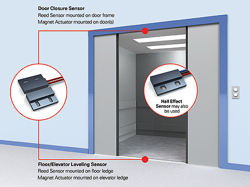
When the door is open, the reed sensor is left with its contacts open, so cannot sense the magnetic field. Its output value feeds into a microprocessor control to indicate an open door. When the door closes, the sensor detects the proper magnetic field and the reed contacts close, sending a new signal to the controller. In modern industrial systems, a microcontroller is usually part of the control circuit. This lets the reed or Hall-effect sensor switch with low logic-level dc voltage and current values.
Basics of digital Hall-effect sensors
These sensors combine a Hall-effect sensing element with circuitry to output a digital on/off signal that corresponds to a change in the magnetic field without using moving parts. The Hall effect device’s active circuitry draws a small amount of current at all times.
Benefits: Digital Hall-effect sensors offer high reliability and users can program them to activate at a given magnetic field tolerance for precise sensing requirements.
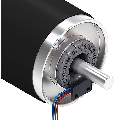
Applications: Hall-effect sensors only work in industrial and motion-control applications with low dc voltage and current values. These sensors are common in high-speed applications such as rotary speed tracking on linear conveyors. For example, a Hall-effect speed sensor might detect a rotating 16-pole ring magnet. Here, the Hall-effect sensor activates with each passing north-pole segment and deactivates with each passing south-pole segment. Then the sensor sends these signals to the control unit.
High-precision analog sensors: Rotary and linear Hall effect
Analog sensors let end users get instantaneous feedback on a magnet’s position in an industrial system. Analog Hall-effect sensors of the past measured the flux density of the magnets and are greatly influenced by the temperature value of the application. Now, thanks to advances in analog Hall-effect technology, newer Hall-effect chips measure the angle of the flux field instead of the traditional amplitude, making them much less sensitive to temperature changes. So, the sensors deliver more stable analog output across a large temperature range.
There are a couple Hall-effect sensor variations that are suitable for custom analog sensing.
Basics of rotary Hall-effect sensors
Without using any moving parts, this semiconductor-based sensor combines a Hall-effect sensing element with circuitry to provide an analog output signal that corresponds to changes in a rotating magnetic field. This sensor offers two output options—analog or pulse-width modulation (PWM).
The device is programmable so engineers can associate a specific output voltage or PWM to a precise degree of rotation. Multiple programming points are available up to 360° of rotation. Each programming point represents a voltage or PWM output value that corresponds to a given angle of the magnetic field. This results in a high-accuracy, high-resolution ratiometric output signal relative to the degree of rotation.
Benefits: Unlike a mechanical rotary or resistive film rotary device, rotary Hall-effect sensors do not experience changing resistance values or mechanical wear. They offer exceptional stability over normal operating temperatures up to 105° C. Units are accurate from 0 to 360° rotation with 0.5 V to 4.5 Vdc output or 10 to 90% duty cycle for PWM.
Applications: Rotary Hall-effect sensors are becoming increasingly popular for replacing resistive film and potentiometers—mechanical devices subject to wear and oxidation that degrade signals in the control unit. So, Hall-effect sensors work in myriad motion designs. For example, they can help measure the angle of a flapper valve in a fluid-flow system to precisely adjust the flow rate; in control circuits, they work to detect dial position.
Basics of linear Hall-effect sensors
Linear Hall-effect sensors measure linear movement of a magnetic field rather than rotation. Such sensors are programmable for a set output voltage that is ratiometric for a given travel distance. (Their output options are the same as those for rotary Hall-effect sensors.) The sensors measure linear movement and relative flux angle of magnetic actuators to 30 mm of travel with a single Hall-effect chip. This outputs a ratiometric signal to track the precise movement of the sensor.
Benefits: The sensor and actuator work in all sorts of final mounting areas, even where they’re subject to magnetic influences from surrounding equipment. This makes for an optimal output signal because programming can account for any shunting, mechanical tolerances or stack-up tolerances of the magnetic field (so the output signal corresponds to just the magnetic-flux direction as the magnet rotates).
Applications: Linear Hall-effect sensors often work as level sensors for monitoring fluid levels. Here, the sensor detects the location of a moving float sporting a magnet. Linear sensors can also be useful when seeking a precise position tolerance for automatic pick-and-place systems.
Expertise applied: Custom sensing for a conveyor
When selecting high-performance magnetic sensing, first the design engineer should conduct a thorough review of the application’s environmental, mechanical, electrical and magnetic parameters. Then the engineer should analyze the industrial application’s full magnetic circuit—including the sensor and magnetic actuator. Then the engineer can identify custom-sensor setups robust enough to meet the design requirements.

Employing the design guidelines and best practices we review here, consider the following case study in which a custom magnetic sensor improves an industrial-conveyor application.
The problem: Initially, the machine builder wanted a Hall-effect speed sensor mounted to an industrial belt-drive system on a conveyor. Extensive communication between the end user and design-engineering teams made it clear that a standard Hall-effect sensor wouldn’t meet the requirements for electromagnetic compatibility (EMC), electromagnetic interference (EMI) or electrostatic discharge (ESD), because the electric motor running the conveyor was too close to the sensor’s location.
Other requirements: The end user needed a custom sensor setup with 24-AWG insulated lead wires connected to the standard Hall-effect sensor through an uncontrolled environment. The lead wires had to withstand potential hazards within the factory such as dust, chemicals, oils and vibrations. They also had to continuously send speed signals to a microprocessor control unit.
The Hall-effect speed tracking had to be upgraded to handle the speed and relative magnetic circuit of the sensor’s actuator. The sensor had to bridge the required 2-mm gap between the sensor and the magnet.
The solution: The engineering team developed a robust custom design with additional capacitive and resistor circuitry on a printed circuit board. That gave the sensor extra EMI, EMC and ESD protection. The sensor’s injection-molded capsule was made larger than the standard capsule to accomodate the new circuitry. In addition, the lead wires were upgraded to 20 AWG with Teflon insulation.
The manufcturer designed a true speed-sensing Hall-effect chip to replace the digital Hall-effect chip and get more accurate speed signals.
The design team also used computer simulation to identify the optimum magnet design for the 2-mm sensing gap. They determined that a 16-pole toroid magnet (with eight pole pairs) would maximize magnetic-circuit reliability. So now, the new injection-molded capsules work for other designs without forcing the end user to pay for tooling.
Littelfuse
www.littelfuse.com

Leave a Reply
You must be logged in to post a comment.