
Linear bushings (also referred to as ball bushings, or, more generically, as linear bearings) are round linear guides with circuits of recirculating balls that ride on a precision steel shaft. Linear bushings provide good load-carrying capacity with very low friction, but despite their simple design and easy installation, sizing a linear bushing is not a straightforward endeavor. There are many factors that affect linear bushing life, and if these parameters aren’t taken into account during sizing, the result could be a product that’s undersized for the application or that has a lower than expected travel life.
Below are some of the most common factors that influence bushing life, and an explanation of how to account for them during selection and sizing.
Linear bushing load orientation
Linear bushings are unique in that they can rotate around their shaft, meaning that the position of the ball tracks, and thus, their load carrying capability can vary. The maximum capacity is achieved when the load is carried by the highest number of tracks possible. This means that the optimum bearing and load orientation depends on the number of tracks and whether the bearing is an open or a closed type.
In order to account for the various bearing and load orientation scenarios, most manufacturers provide polar graphs that give an orientation correction factor for each angle of deviation from a reference case. Other manufacturers provide a table showing correction factors for the two most common orientation cases: load applied directly above one row of balls, and load applied directly between two rows of balls.
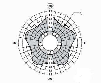
Image credit: Thomson Linear
The correction factors are specific not only to each manufacturer, but also to individual designs of linear bushings, so it’s important to be sure that you have the right graph or table for the specific bushing in question. It’s also important to note that the correction factor can be greater than one (meaning that in certain load orientations, the bearing’s load capacity will be greater than the standard, published load capacity), or less than one (reducing the published load capacity).
Linear bushing travel life expectancy
Like other recirculating bearings, the dynamic load capacity of a linear bushing is based on a predetermined travel distance—typically 2 million inches, or 100,000 meters. (Note that some manufacturers base dynamic load capacity on 50,000 meters.) Because linear bushings are often expected to achieve a travel life far exceeding the rated values, manufacturers provide a travel life correction factor for the dynamic load capacity. For example, if the dynamic load capacity is based on 100,000 meters, but the required life is actually 1,000,000 meters, a load correction factor in the range of 0.4 to 0.5 may be necessary.
Linear bushings working over short strokes
If a linear bushing travels only a short distance, the repeated wear, concentrated on a small area of the shaft, will reduce the life of the shaft in comparison to the life of the bushing.
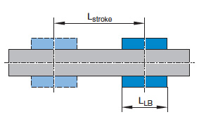
Image credit: Bosch Rexroth Corporation
This situation is known as a short stroke application, and is typically defined as a stroke that is less than two (or, for some manufacturers, three) times the length of the bushing. In these applications, a short stroke correction factor must be applied to the dynamic load capacity of the bushing.
Shaft hardness
Unlike their profiled linear bearing counterparts, linear bushings and shafts are not matched sets. That is, the bushing and shaft can each be supplied by different sources. Linear bushing manufacturers commonly provide steel shafting with a hardness of HRC58 or HRC60. But when shafting is obtained from an alternative source, or if a different composition is used, the hardness can vary. For example, 420 stainless steel can have a hardness as low as HRC51, while 440C stainless can have a hardness of HRC61. In this case, a shaft hardness correction factor must be applied, to account for accelerated wear due to the softer material. Note that shaft harness correction factors are typically given for both dynamic and static load capacities.
Other linear-bushing considerations
Although less common, other application-specific parameters can reduce linear bushing life, and many manufacturers offer correction factors for these as well. One such example is a temperature correction factor. Seals and other plastic components in linear bushings often limit their use to temperatures up 85 degrees C (100 degrees C for some products). For higher temperature capabilities, one option is to use a bushing with all metal components. But if an all-metal design is not feasible, a temperature correction factor can be applied to account for accelerated wear and reduced life. Similarly, correction factors are sometimes given for applications with high shock loads or vibration.
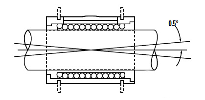
Image credit: Thomson Linear
Another example is a misalignment factor. When shafts are not supported along their entire length, they can experience deflection, which causes misalignment of the bushing relative to the shaft. This is especially problematic if the bushing is not a self-aligning type, as it results in uneven loading on the load-carrying balls. If misalignment exceeds a given value (but remains below the maximum allowable), then a misalignment factor must be applied to the dynamic load capacity.
Linear bushings are the original recirculating linear ball bearings, and their suitability to a wide range of applications has helped them maintain popularity for all types of industrial and consumer installations. Because of this, manufacturers have extensive knowledge of how they behave in unconventional or challenging situations, as shown by their ability to quantitatively address almost any application scenario.
Feature image credit: PBC Linear


Leave a Reply
You must be logged in to post a comment.