Certain approaches simplify the sizing, integration, and protecting of tubular linear motors destined for thermally constrained applications — and they don’t necessarily rely on the use of large and costly motors.
Rebecca McWilliam · Director of engineering — Iris Dynamics | irisdynamics.com
Linear motors behave differently than rotary motors — so how does their electrical power consumption relate to force and heat? Well, current through the windings of tubular linear motors generate magnetic fields that interact with the shaft’s permanent magnets. This interaction prompts force and motion output. There’s a caveat, though — current passing through the windings also generates heat that must be dissipated to prevent damage to the magnetic shaft, integrated electronics, and windings themselves. Even when damage isn’t imminent, this thermal behavior impacts the motors’ performance in advanced automation, robotics, and precision motion systems. Fortunately, there are way to reduce the thermal load with motion design, duty cycling, and cooling (whether passive or active).

Motor power and heat-generation definitions
For this discussion, we define steady-state temperature as the resultant motor temperature for a given power input that fluctuates no more than ±1° C over 30 minutes. Maximum force is that output by a linear motor when operating at maximum power. Continuous force is that output by a linear motor when operating at a given power.
Maximum power is that dissipated by a linear motor when operated at its peak output, which is only sustainable for a short period of time. Continuous power is the power dissipated by a linear motor when operated at steady state temperature for an indefinite period of time without overheating. Maximum continuous power is that dissipated by a linear motor in a room with still air at 20° C that brings the linear motor to a steady-state 70° C.
Long periods of high power draw, transient high-force events, hot environments, and impeded airflow can all cause excessive motor heating and thermal shutdown.
Force-power relationship: Motor force output is proportional to current, while resistive heating power scales with current squared — Force² ∝ Power. So, modestly reducing motor-force demand dramatically reduces heating. For example, halving force demand trims power dissipation to 25% while doubling the force increases heating fourfold. So, integrating mechanical components such as gears, pulleys, or leadscrews imparts an exponential reduction in thermal power.
Thermal limitations: Linear motors can be thermally limited by integrated electronics, magnets in the shaft, copper windings, and (in some cases) the need to maintain safe operating temperatures for machine personnel who may touch the motor. Most heat generated by a linear motor originates in the coil — with the amount directly proportional to power input and force output.
Tubular linear motors like other linear-motor subtypes have long thermal time constants (to minutes long) thanks to large thermal mass and relatively slow conduction from windings to housing to ambient air. So, they can tolerate high-force demands that are brief sans immediate risk of overheating, because the windings’ heat takes so long to raise the overall motor or integrated electronics’ temperature to dangerous levels. However, this also makes average power over some multi-minute interval a key expression of thermal stability.
Despite a long overall time constant, spikes in power draws can cause windings to exhibit rapid and localized heating. After all, copper coils react almost instantly to current heating — far faster than thermal energy can spread into the stator or chassis — meaning they can exceed their safe temperature limits even before the housing becomes warm.
Measures to prevent motor overheating
To prevent windings from overheating, feedback can keep input power to below thermal thresholds or cut power entirely if needed. Feedback can come from:
- Temperature sensors directly bonded to the coils for accurate feedback. Note that PCB-based temperature sensors can protect against accidental overdriving, but there’s a delay between coil energization and measurable warming of the PCB.
- A motor driver that integrates a joule counter. These use a thermal model to estimate realtime winding temperature and enforce safe limits.
Thermal shedding is another way to keep motors within thermal limits — by flowing heat from windings to stator to chassis (housing) to environment. Ambient temperature, airflow, and enclosure design directly affect how effective this shedding is. Fans boost convective cooling … and external motor fins, heat sinks, and conductive mounts boost conductive and radiative heat transfer. These together affect heat shedding and the continuous and intermittent force a motor can safely deliver.

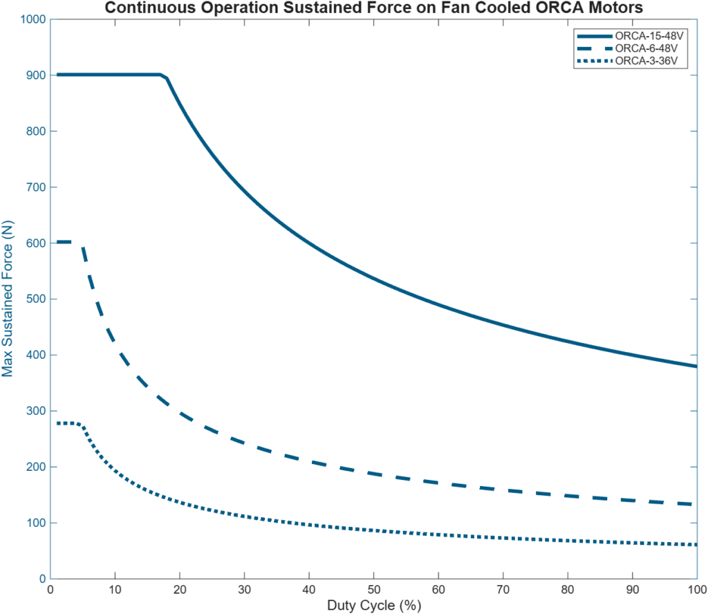
Maximum vs. continuous power draw: Winding design, supply voltage, and electronics dictate maximum instantaneous power while motor thermal limits dictate maximum continuous power. Higher powers are okay for brief periods if average power remains below the continuous rating. For example, outputting 120 W for 60% of the time and 70 W for 40% of the time results in an average power of 100 W.
Thermal capacity: Motor copper, epoxy, and chassis can all safely absorb a certain amount of heat … yet eventually, heat saturates the assembly with heat energy Q = C⋅ DT where C is the motor’s overall thermal capacity and DT is the change in temperature.
Thermal shedding: The efficiency with which heat transfers from motor windings to the environment ultimately governs the continuous force rating. This largely depends on motor housing surface area which in turn depends on motor size.
Kf’ motor force constant: This expresses the efficiency with which a motor turns power into force in Newtons per square root Watts. A motor with a higher Kf’ means the motor will output more force for a given power draw. Kf falls as winding resistance climbs, and resistance increases with temperature (as power loss Ploss = I2R) so generating a given force at hotter temperatures takes more current. In fact, this is the cause of thermal runaway.
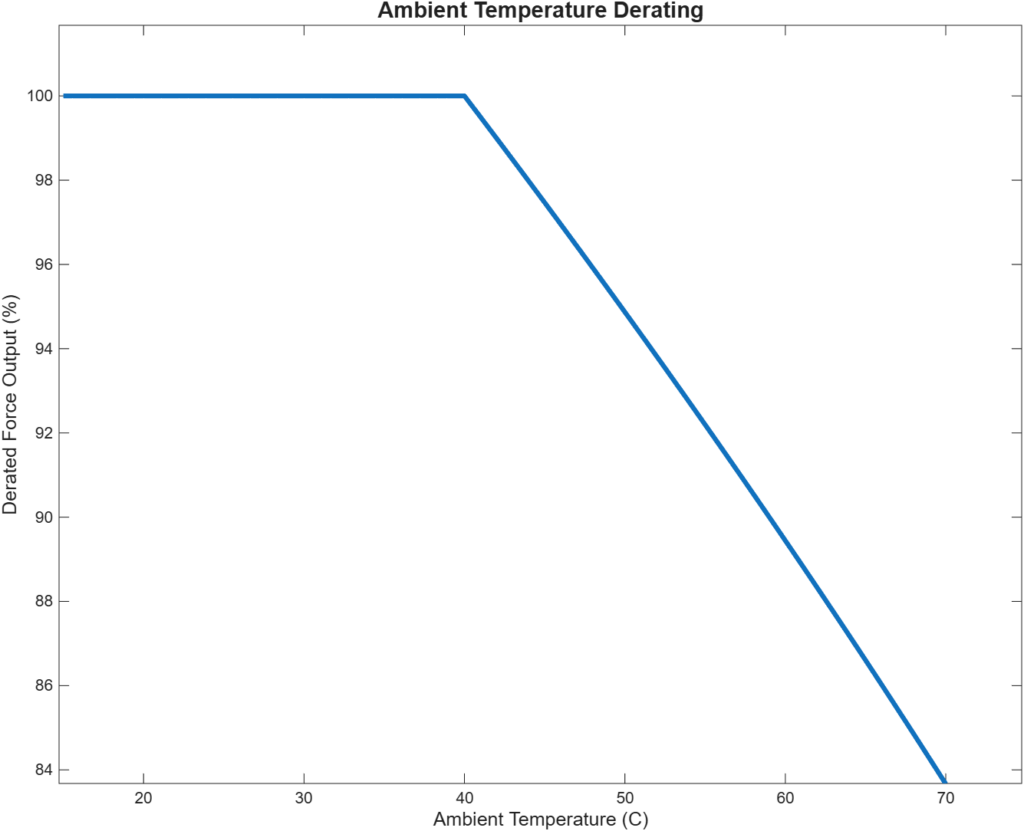
Ambient temperature: When a linear motor must operate in a hot factory setting or in a confined space, its force must be derated, and a larger motor may be required. The required amount of derating depends on ambient temperatures:
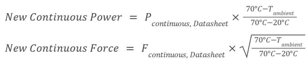
As ambient temperature approaches the motor’s thermal limits, the acceptable amount of time for maximum power is more and more brief until it’s only instantaneously possible.

Ways to mitigate heat issues
Decrease average power: Effective thermal management starts with reducing average power draw because root-mean-square RMS force rather than instantaneous peak force causes sustained heating. Reduction is possible with gentler accelerations, smoother motion commands, reduced holding duty cycles, or and more mechanical advantage (as with spring or pneumatic assistance).
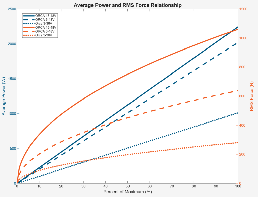
Reduce duty cycle: Shortening the duration of high-force events or spacing them farther apart can dramatically lower overall power draw and thermal load even when peak forces stay high. Rest periods leverage the motors’ long thermal time constants so accumulated heat is more effectively shed.

Decrease peak force: Lower peak-force demand reduces instantaneous current spikes that can cause rapid coil heating. Lowering peak force by half trims power draw by three-quarters. For example, outputting 200 N with a force constant of 15 N/√W takes 178 W. Outputting 180 N with 15 N/√W takes 144 W. Outputting 100 N with 15 N/√W takes 44 W.
Pneumatic and spring support: Where springs and pneumatics complement tubular linear motors to reduce power consumption, some controls’ PID loops settle to prompt only the force needed to hold position. Springs can introduce temperature-related performance drift, but for many tubular linear motors, spring-force offset can help trim power consumption. Plus, as long as the motor can apply enough force to fully compress or extend the spring, the latter is easy to calibrate so the axis still allows force sensing.

Cooling airflow: Some tubular linear motors have cooling fins on their housings for a large heat-dissipating surface area. If a fan is also used, its cooling effectiveness increases with stator size (and surface area). A single fan can increase continuous maximum power threefold (for smaller motors) to fivefold (for larger motors). More airflow boosts continuous maximum power, though with diminishing returns … especially in enclosed spaces where climbing ambient temperature can degrade cooling effectiveness.
Tubular linear motors mounted so all housing sides are exposed allows uniform convective cooling. Any installation that obstructs airflow to housing sides reduces the effective cooling surface.
Water cooling: Some tubular linear motors are IP68 rated, so can be cooled with water over the cooling fins. Water spray, constant overflow, or even full submersion can dramatically boost thermal performance.
This article is an adaptation of an Iris Dynamics piece. Check out other Iris Dynamics tutorials at irisdynamics.com/engineering-resources.

Leave a Reply
You must be logged in to post a comment.