Linear actuators are available in configurations that address virtually any application – rail, shaft, or cam roller guideway; screw, belt, or linear motor drive; with or without protective covers; and a wide variety of features to meet unique environmental or technical requirements. All these options make it relatively easy to find the right actuator for your application. But once you find the best configuration for your needs, fitting it into the available space in the machine or system can be a more difficult challenge. The three considerations below can help overcome space constraints without compromising performance.
Motor Mounting
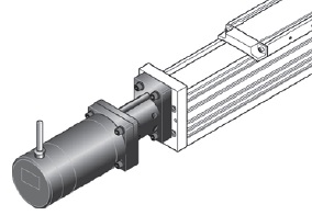
A wide variety of methods for attaching the motor to the actuator makes this the first place to look for space-saving ideas. For ball screw driven actuators, the standard attachment method is to mount the motor directly to the screw shaft, via a motor mount and coupling. This puts the motor inline with the actuator and significantly increases the length of the assembly. To alleviate this problem, a timing belt and pulley system (often referred to as a “side drive”) allows the motor to wrap under, above, or to either side of the actuator, minimizing the additional length and adding only a small increase in width (or height, depending on orientation). By using a smaller pulley on the motor shaft than on the screw shaft, a side drive can also provide gear reduction – typically 1.5:1 or 2:1 – to better match the motor inertia to the inertia of the actuator and applied load.


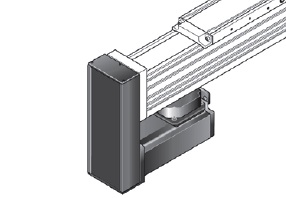
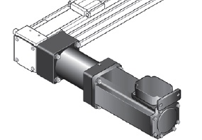
In belt driven systems, mounting the motor directly to the drive shaft increases the width of the system, since the drive shaft is perpendicular to the belt and pulley assembly. Due to large pulley diameters and lead constants (distance traveled with each pulley revolution), belt driven actuators often use a gear reducer, which further increases the system width. A right angle gear reducer can help counter this by allowing the motor to mount parallel to the actuator (in the line of travel). A more compact solution, offered by some gearbox manufacturers, is to integrate the drive pulley directly into the gearbox assembly. This significantly reduces the amount of width that the gearbox adds, and with a female input for the motor shaft, also eliminates a motor mount and coupling, providing further space savings.


Sealing
In some cases, protecting the actuator from contamination, especially liquids and large debris, can be achieved by mounting the unit upside down or on its side, without any additional hardware. But when airborne particles or fine dust are present, a secure cover is the best way to protect internal components.
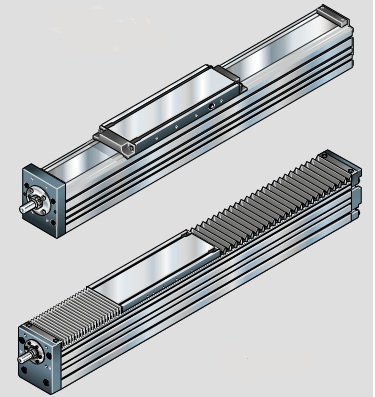
The original covering method for linear actuators was to install accordian-style bellows, typically made of polyurethane. But bellows can add nearly 20 percent to the length of the actuator, making them less than ideal for applications with limited space. An alternative solution is to use a stationary cover strip, made of either rubber or stainless steel.

Unlike bellows, stationary cover strips require only a small amount of additional space – typically 150mm or less – to account for hardware to clamp the strip at its ends and to guide it through the bearing table. And because they mount flush with the top of the extrusion or body of the actuator, sealing strips don’t add to the width or height, and they provide excellent sealing characteristics.
Safety Travel
Safety travel is added in case the machine or system encounters an emergency stop. Its purpose is to provide some travel length beyond the maximum required stroke, allowing the bearing table to stop without hitting the ends of the actuator. A rule of thumb for safety travel is two turns of the motor on each end of the actuator, or four turns total. For a ball screw driven actuator, this will be four times the lead of the screw, and for a belt driven actuator, this will be four times the lead constant of the pulley.
So how does safety travel contribute to saving space? A mistake that is often made when calculating safety travel is neglecting to account for any gear reduction that is being used with the actuator. When a gear reducer is used, each turn of the motor translates to a proportionally smaller amount of travel for the bearing table. For example, a belt driven actuator with a lead constant of 90mm would require 360mm of safety travel (2 x 90mm on each end of the actuator, or 4 x 90mm total). But if a 3:1 gearbox is used, each turn of the motor will result in only 1/3 rotation of the pulley, or 30mm of travel. This reduces the total amount of safety travel to 120mm (4 x 30mm). Accounting for gear reduction can yield a substantial savings in length without compromising the desired safety travel.
With factory layouts increasingly designed around lean principles, the footprint of a machine or system is an important factor in its selection. No matter what type of actuator you’re using, a few considerations in the design and selection stage can ensure it meets not only the technical requirements, but also the space constraints of your application.
Illustrations courtesy Bosch Rexroth Corporation. Used by Permission.


Leave a Reply
You must be logged in to post a comment.