Today servomotors abound. Thankfully the art of using speed, torque, and inertia to select from these servomotor offerings for specific applications has become quite automated.
By Sixto Moralez • Regional motion engineer | Yaskawa America Inc. Drives & Motion Div.
Now, certain sizing and selecting software only requires that design engineers enter a minimum of data to identify a plethora of servomotor products suitable for the motion design at hand. In this article, we illustrate how the process works by using one advanced software tool and walking through the steps of a specific example.
Motion system design Step 1: Mechanical selection
Most machine builds can be modeled as basic mechanisms. Some software is preprogrammed to ask for the machine-axis mechanism type and then send the engineer to a set of fields to define its parameters.
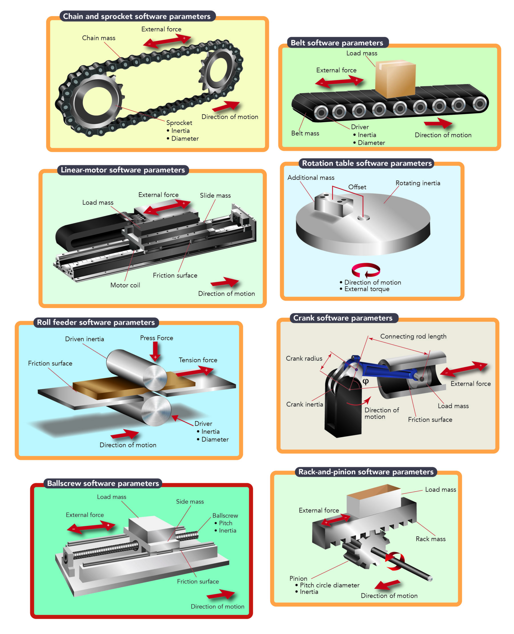
Case in point: One common power-transmission device for linear motion is the ballscrew. Most ballscrew-based designs employ a rotary servomotor that is coupled to the ballscrew by a flexible aluminum coupling. Then the linear drive moves a load carriage that slides on linear rails to move a payload back and forth. Let’s use this example through the remainder of this article.
Motion system design Step 2: Gathering and entering data
Getting information from end users or potential customers can sometimes be challenging. However, design software gives engineers in this position the ability to visually see and enter data as it becomes available. Then the software automatically identifies which servomotors are capable of serving as the motion input for the application. Assuming our ballscrew-driven arrangement, these parameters include total load and slide mass, which is usually a combined number … but can be based on various parameters upon which separate load mass and slide mass values are based. Refer to the software screenshot titled, “Total load and slide mass — entering data on ballscrew in the software” for example values.
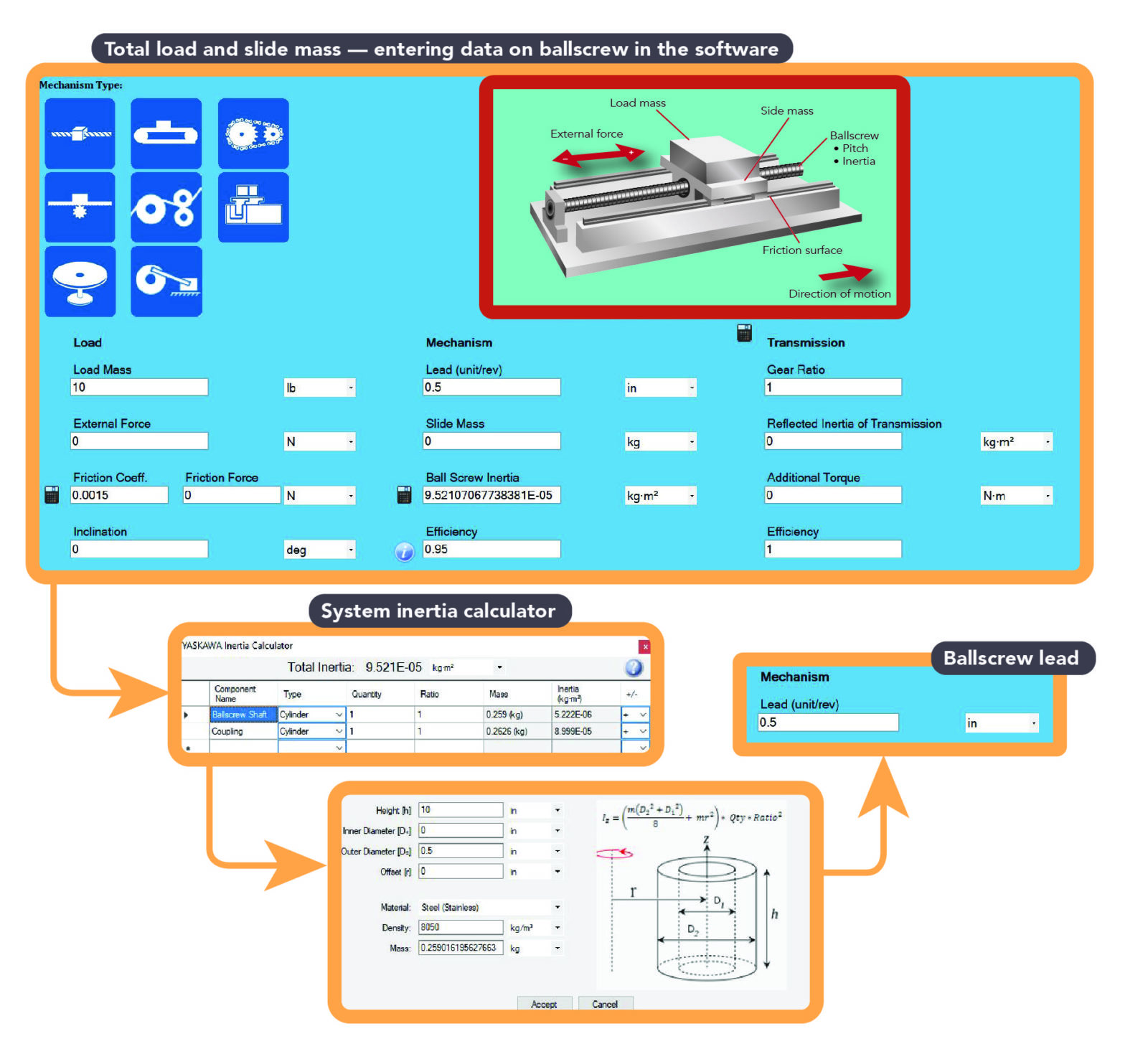
After entering these first values, the engineer should factor the inertia of the ballscrew into the design. If this isn’t given by the customer or manufacturer, use the software’s ballscrew inertia calculator to determine the inertia of the ballscrew.
Then the engineer should enter the lead of the ballscrew. This is the number of units (inches or millimeters) the ballscrew travels in one revolution.
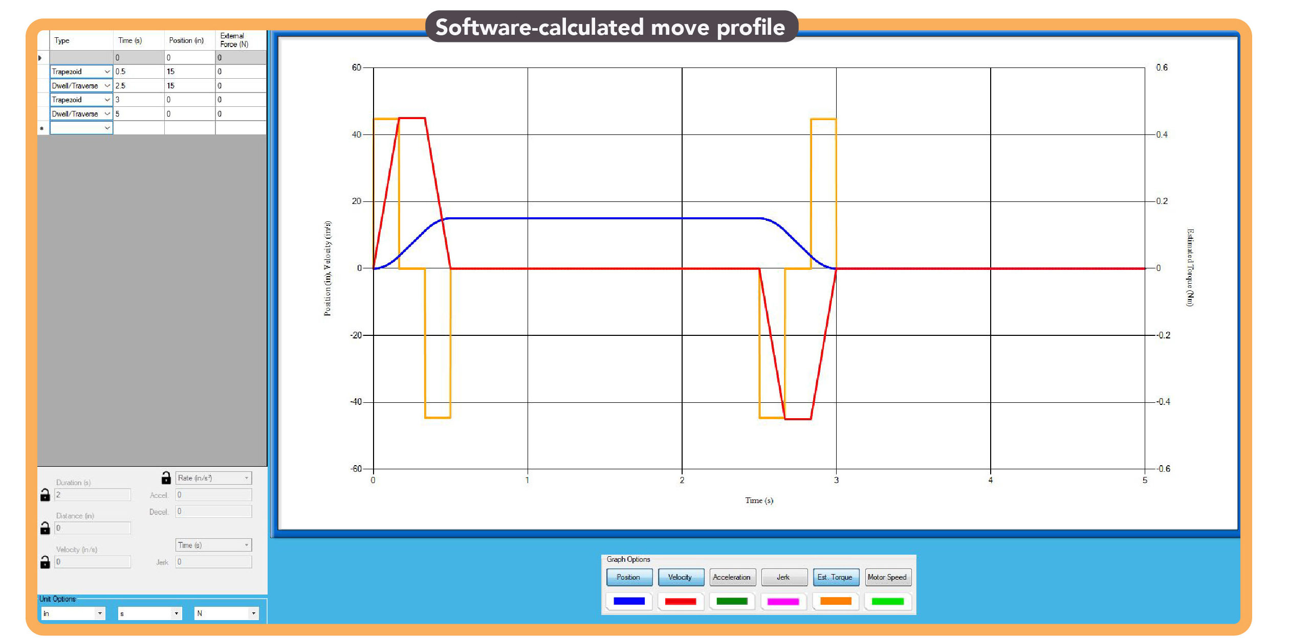
After inertia and lead values are set, the engineer should define the application’s move profile. Here, he or she enters the distance to move and in what amount of time — including any dwells or pauses. It is also good practice to enter a return move.
Motion system design Step 3: Selecting a motor
With all the information entered, sometimes design software will return a sizable list of servomotors that are suitable for the application.
In this case, if cost is an issue (and it usually is) sort the suggested motor results by the cost factor to find the lowest (initial) cost servomotor that will satisfy the application requirements.
Something else to leverage in some software is the ability to corollate the design’s cost factor to the factor of safety. In many cases, spending just 10% more on the initial servomotor purchase can give the application an additional 20% on its factor of safety. Upsizing in this way allows for future scope creep — a common occurrence for motion systems.
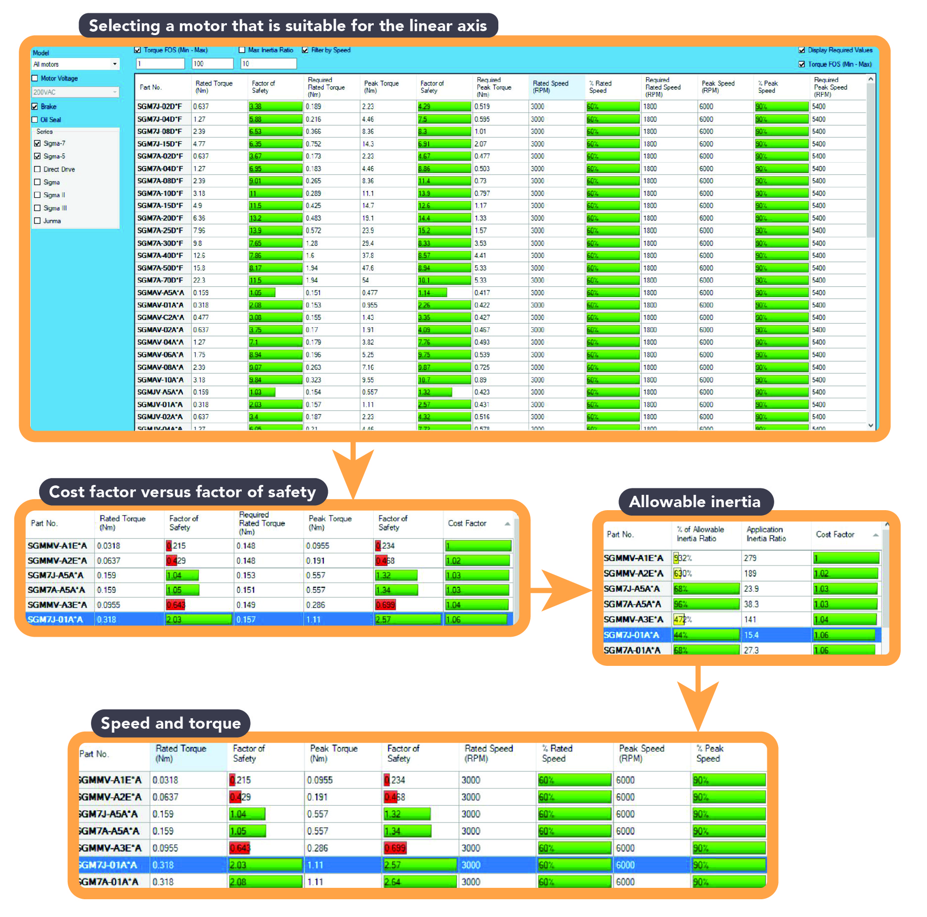
Regarding the speed and torque values: If the application requires more speed but not a lot of torque, an engineer employing the above data should choose SGM7J or SGM7A motors. Conversely, if the application requires more torque and not a lot of speed, an engineer employing the above data should choose an SGM7G motor. Some applications can have dimensional constraints; these would benefit from the specification of SGM7P servomotors.
Next, verify that the inertia ratio is at or below the allowable inertia ratio number. Refer to the software screenshot labeled “Allowable inertia” for an example of how these results appear — in this case, highlighted in green in the allowable inertia-ratio column. For our ballscrew-based design and motor selected in the screenshot, the design’s load inertia ratio divided by the servomotor’s motor inertia is 44% — which is great for the application.
Third, verify the speed and torque of the application is at or under the motor’s maximum allowable values. (Motor manufacturers offer different series of servomotors for different applications to make this step easier.) Note in the screenshot labeled “Speed and torque” that our chosen motor’s speed and torque ratings exceed those of our application.
Motion system design Step 4: Account for any power-transmission additions to the assembly
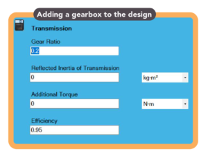
Let’s say the motor chosen is an expensive servomotor. Remember, our sizing was done as a servomotor directly coupled to the ballscrew. But what if the application can accept the use of a gearbox with a 5:1 ratio? No worries because the design software is flexible and lets the engineer go back and enter new data. Let’s enter the following for the gearbox characteristics:
Ratio (input to output) for 5:1 gear ratio in the software is entered as 0.2. Inertia can be in in.lb × sec2 or kg × m2 and efficiency is typically between 95% to 97% or so.
Then the engineer goes back to the motor selection to choose a different servomotor.
Oftentimes this step will result in a selection of a smaller servomotor, because gearboxes multiply the torque by the ratio number; reduce the inertia by the square of the ratio; and help the design stay within the application’s speed constraints.
Motion system design Step 5: Regeneration and drive requirements
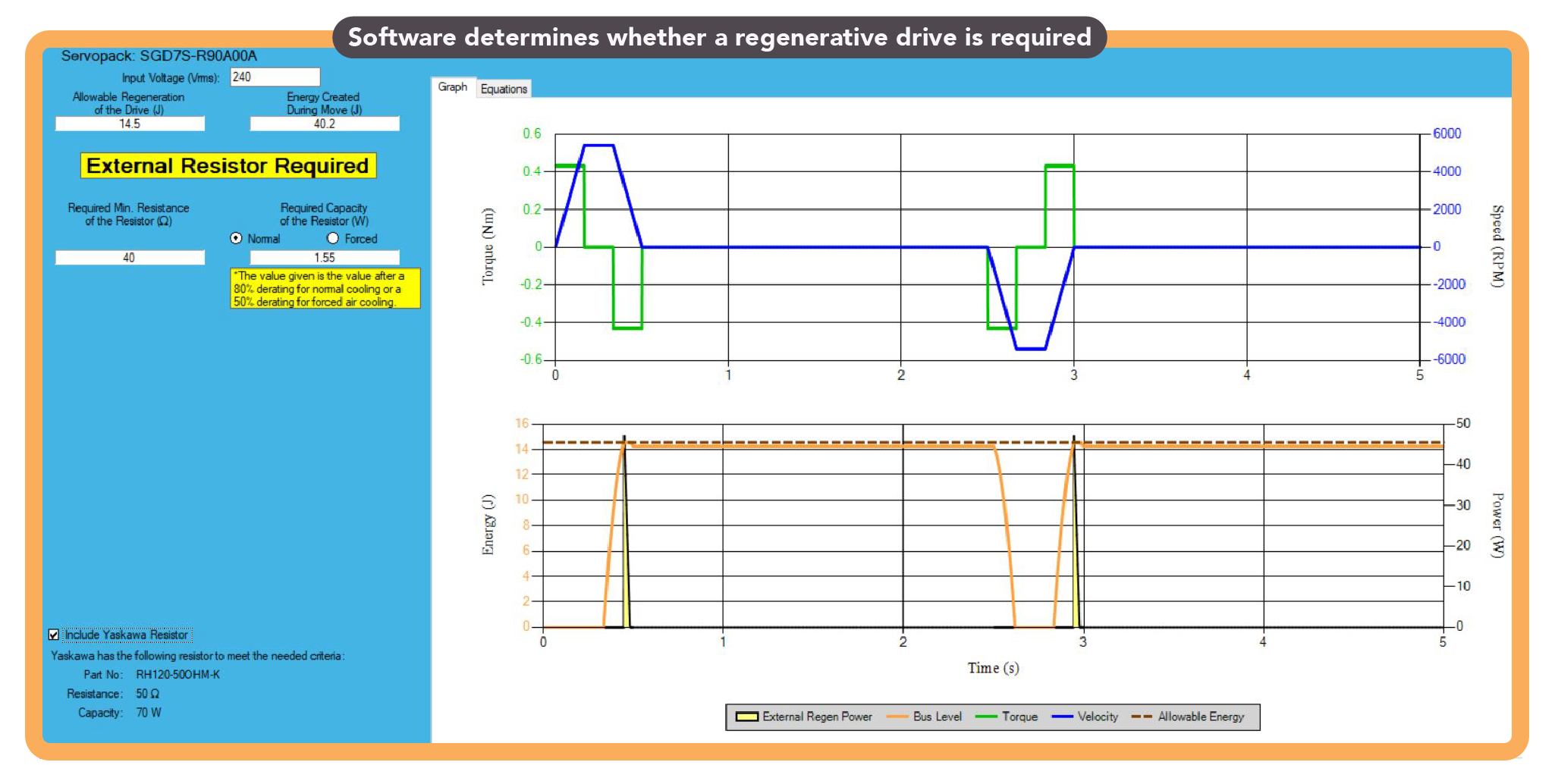
Software from some manufacturers will indicate if a regenerative resistor is needed and what capacity should be selected. Some will also list compatible drives with sufficient networking and connectivity features.
Motion system design Step 6: Generating reports for sharing
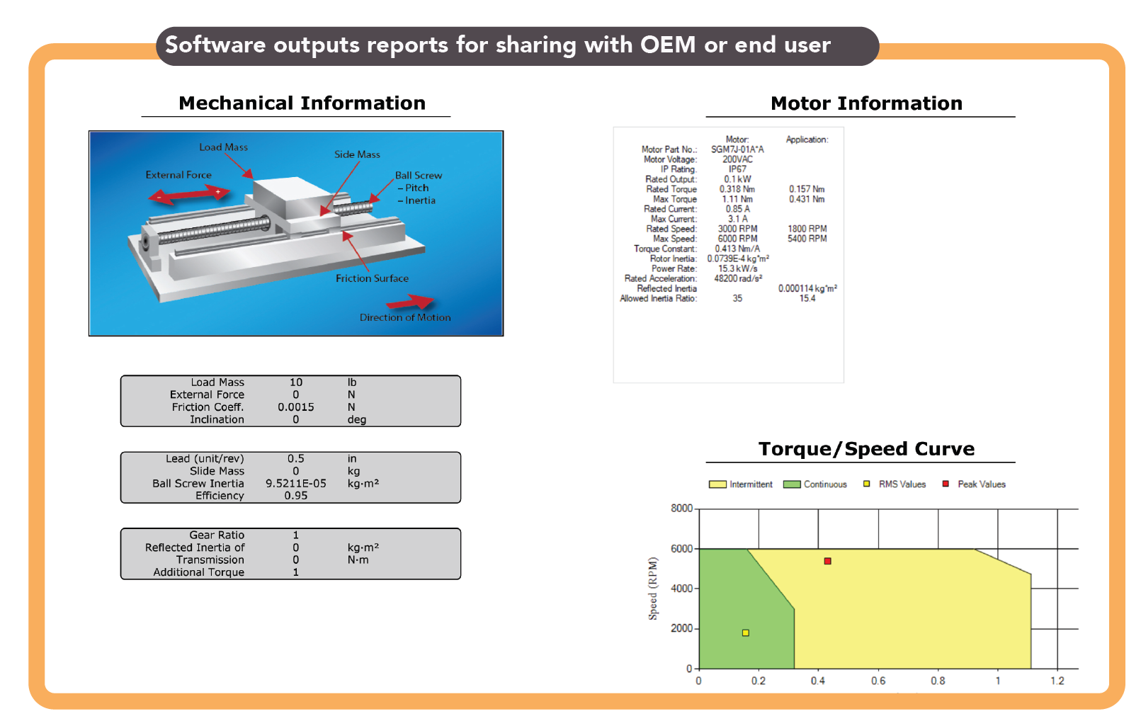
Most servomotor sizing and selecting software includes the ability to output full design reports to share with clients for data verification.
For more information, visit yaskawa.com/products/motion/sigma-7-servo-products.




Leave a Reply
You must be logged in to post a comment.